Table of Contents
Advertisement
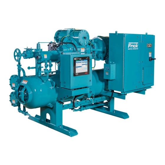
Rotary Screw Compressor
Models 100 to 1080
This manual contains installation, operation, and maintenance
instructions. Read thoroughly before beginning installation. Failure
to follow these instructions may result in personal injury or death,
damage to the unit, or incorrect operation.
Check www.FrickCold.com for the latest version of this publication.
Form 070.610-IOM (JUL 2021)
Installation–Operation–Maintenance
File:
Replaces:
Distribution: 3, 3a, 3b, 3c
RWF II
All Refrigerants
Service Manual – Section 070
070.610-IOM (MAR 2020)
Advertisement
Table of Contents
Troubleshooting

Related Manuals for Frick RWF II 100


Summary of Contents for Frick RWF II 100
- Page 1 Form 070.610-IOM (JUL 2021) Installation–Operation–Maintenance File: Service Manual – Section 070 Replaces: 070.610-IOM (MAR 2020) Distribution: 3, 3a, 3b, 3c RWF II Rotary Screw Compressor All Refrigerants Models 100 to 1080 This manual contains installation, operation, and maintenance instructions. Read thoroughly before beginning installation. Failure to follow these instructions may result in personal injury or death, damage to the unit, or incorrect operation.
-
Page 2: Table Of Contents
070.610-IOM (JUL 21) RWF II Rotary Screw Compressor Units Page 2 Installation - Operation - Maintenance Table of Contents General information Suction check valve power assist kit ....... 31 Balance piston pressure regulator ........31 Preface ................3 Initial start-up ..............31 Design limitations .............. -
Page 3: General Information Preface
Regular, systematic maintenance unit data plate containing unit model, serial number and To ensure correct installation and application, select and Frick sales order number is mounted on the side of the connect the equip ment to a correctly designed and installed Quantum ™... -
Page 4: Compressor Identification
070.610-IOM (JUL 21) RWF II Rotary Screw Compressor Units Page 4 General Information Compressor identification Rotary screw compressor serial numbers are defined by the following information: Each compressor has an identification data plate (see below), containing compressor model and serial number Example: 10240A90000015Z mounted on the compressor body. -
Page 5: Installation
Use only the certified general arrangement drawings from Frick to determine the mounting foot locations and to allow for recommended clearances around the unit for ease of operation and servicing. -
Page 6: Skid Removal
070.610-IOM (JUL 21) RWF II Rotary Screw Compressor Units Page 6 Installation Compressor/motor coupling The unit can be moved with rigging, using a crane and spreader bar, by hooking into the four lifting eyes on the installation oil separator. If a motor is mounted, ap propriate adjust- The RWF II unit has compressor to motor alignment ment in the lifting point should be made to compensate through the use of a machined cast iron tunnel. -
Page 7: Oil Pump Coupling
RWF II Rotary Screw Compressor Units 070.610-IOM (JUL 21) Installation Page 7 Install the locknut until it is snug. Make sure that all bolt 1. Inspect the shaft of the motor and compressor to en- threads are clean and lightly oiled. Do not torque any lock- sure that no nicks, grease, or foreign matter is present. -
Page 8: Piping Connections
See the Foundation section for additional information. See Figure 7. Using a pressure-type pump and the recom- mended Frick oil, open the drain valve and pump oil into WARNING the separator. -
Page 9: Oil Filters
16 amp circuit breaker in the micro enclosure is turned off. Oil filters NOTICE Use of filter elements other than Frick may cause warranty claim to be denied. The oil filter(s) and coalescer element(s) shipped with the unit are best suited to ensure proper filtration and operation of the system. -
Page 10: Liquid Injection Oil Cooling - Optional
070.610-IOM (JUL 21) RWF II Rotary Screw Compressor Units Page 10 Installation Figure 9: Thermosyphon receiver system NOTICE The component and piping arrangement shown in Fig- ure 10 is intended only to illustrate the operating prin- ciples of thermosyphon oil cooling. Other component layouts may be better suited to a specific installation. -
Page 11: Water Or Glycol Oil Cooling - Optional
De- termine the size of the oil cooler supplied with the unit, as outlined on the Frick P&I diagram and general arrange- ment drawings. The water or glycol supply must be sufficient to meet the required flow. - Page 12 The strainer must be strong enough to handle the gas pulsations from the compressor. Johnson Controls- Figure 13: Shell and coil economizer system Frick recommends an R/S or Hansen strainer. Also, piston-type check valves are recom mended for instal- lation in the economizer line, as opposed to disc-type SUCTION check valves.
-
Page 13: Economizer Load Balancing
ECONOMIZER of the powermizer option. If the powermizer option is VESSEL HV-2 selected, Frick provides a factory mounted and wired pressure transducer on the economizer inlet. Economizing with VSDs Economizing on a variable speed machine can present challenges. At low load conditions, the mass flow through... -
Page 14: Motor Starter Package
Motor starter package Voltage protection NOTICE CAUTION Johnson Controls-Frick does not advise nor support The motor is supplied with copper ring-type lugs the use of UPS power systems in front of the crimped on the motor leads. These lugs are intended Quantum ™... -
Page 15: Current Transformer (Ct) Ratios
NOTE: REFERENCE 090.040-M QUANTUM HD NOTE: CUSTOMER GROUND REQUIRED MAINTENANCE MANUAL. SEE WIRING DIAGRAM IN 090.040-M PUBLICATION. OPTIONAL CIRCUIT BREAKER FRICK SUPPLIED COMBINATION DISCONNECT CONSULT STARTER AND MOTOR WIRING DIAGRAMS STARTER PACKAGE FOR EXACT WIRING CONFIGURATION RWF II • QUANTUM HD... -
Page 16: Installation Of Electronic Equipment In An Industrial Environment
NEC, but are to be used in conjunction with the NEC code and any other applicable codes. With exclusion of the three phase wire sizing, use Frick drawing 649D4743 as a reference for properly sizing con- trol wires and other wiring specifications. -
Page 17: Wire Sizing
RWF II Rotary Screw Compressor Units 070.610-IOM (JUL 21) Installation Page 17 Wire sizing Figure 20: Voltage source circuit to prevent EMI Control power supply wires should be sized one size larger than required for amperage draw to reduce instantaneous voltage dips caused by large loads such as heaters, con- tactors, and solenoids. -
Page 18: Vfd Applications
To install correctly, run a separate, properly sized (10 or 8 required by code will provide better transfer of this noise. AWG typically) insulated ground along with and taken to Johnson Controls-Frick requires that the ground conductor ground with, the three-phase ground at the three-phase meet the following: supply transformer (plant). -
Page 19: Conduit
In addi- An example of this would be the installation of a screw tion, Johnson Controls-Frick requirements must be fol- compressor package where the motor voltage is 480 V lowed where they exceed or match national or local codes. - Page 20 070.610-IOM (JUL 21) RWF II Rotary Screw Compressor Units Page 20 Installation • First, call the panel manufacturer before drilling into ground wires back to the power source (Plant Transform- the panel to be sure you are entering the panel at the er).
-
Page 21: Communications
HD panel. With a UPS system providing shut- ™ operation of the communications as all of the preceding down protection for a Frick Quantum panel, the panel may practices are to the equipment. not see the loss of the three-phase voltage on the motor... - Page 22 070.610-IOM (JUL 21) RWF II Rotary Screw Compressor Units Page 22 Installation This page is intentionally left blank.
-
Page 23: Operation
See the following warning. Operation and startup instructions WARNING The Frick RWF II Rotary Screw Compressor Unit is an inte- Compressor rotation is clockwise when facing the grated system consisting of seven major subsystems: compressor drive shaft. See Figure 25. The compres- 1. -
Page 24: Demand Pump Oil System
070.610-IOM (JUL 21) RWF II Rotary Screw Compressor Units Page 24 Operation compressor is moved by the compressor rotors out the Figure 26: Oil separation system compressor outlet and back to the oil separator. For normal high-stage operation, an oil pump is not required. -
Page 25: Compressor Hydraulic System
RWF II Rotary Screw Compressor Units 070.610-IOM (JUL 21) Operation Page 25 Figure 27: Cold-start valve NOTICE To control the rate of loading and unloading, change cycle time, proportional band, and dead band setpoints with Quantum control. If additional control is needed, throttle SC2 or BP. -
Page 26: Compressor Oil Cooling Systems
070.610-IOM (JUL 21) RWF II Rotary Screw Compressor Units Page 26 Operation Figure 29: Hydraulic schematic - all package sizes SC 4 NOT USED DIRECTION DIRECTION CONTROL CONTROL VALVE VALVE SV-3 SV-2 SV-2 SV-3 SCREW IN FLOW SCREW IN FLOW DIRECTION REGULATING REGULATING... -
Page 27: Quantum Hd Ez-Cool Liquid Injection Adjustment Procedure
(4-10 EZ COOL PI Control mA) signal. This is the standard valve type for Frick [Setpoint] - Enter the value that you wish to control to. packages and includes valves like the Danfoss modulat- [Proportional Band] –... -
Page 28: Operation Of Danfoss Liquid Injection Valve
070.610-IOM (JUL 21) RWF II Rotary Screw Compressor Units Page 28 Operation Operation of Danfoss liquid Figure 33: ICAD parameter list display example injection valve Figure 31: ICAD MMI • Acknowledge and save change of value of a parameter. • To exit from the Parameter list and return to the display of opening degree (OD), keep the push button activated for 2 seconds. -
Page 29: Suction Check Valve Bypass
RWF II Rotary Screw Compressor Units 070.610-IOM (JUL 21) Operation Page 29 Suction check valve bypass Figure 35: ICAD "high" function status The RWF II unit is equipped with a low-pressure-drop suction check valve bolted directly to the compressor housing. Valve NV-2 must be open in most systems at all times. - Page 30 070.610-IOM (JUL 21) RWF II Rotary Screw Compressor Units Page 30 Operation Table 10: Parameter list Description Display Min. Max. Factory Unit Comments (standard setting) name setting ICM OD ICM valve Opening Degree is displayed during normal operation. (Opening degree) Running display value (see j01, j05).
-
Page 31: Suction Check Valve Power Assist Kit
Initial start-up must be performed under the super vision of limits the high pressure gas feed to the suction check a Johnson Controls-Frick authorized start-up representa- valve to thirty seconds via the solenoid valve. This is suf- ficient time to warm the suction check valve piston and tive to prevent voiding the compressor warranty. -
Page 32: Vfd Skip Frequencies
070.610-IOM (JUL 21) RWF II Rotary Screw Compressor Units Page 32 Operation The second method is used for compressors with Liquid until full range is accommodated. Also refer to 070.902-IB Injection Oil Cooling. Because the discharge temperature is for acceptable package vibration readings. controlled by the Liquid Injection Thermal Expansion Valve Review skip frequencies as shown in the Maintenance you will not be able adjust for the correct oil flow by using... -
Page 33: Maintenance General Information
RWF II Rotary Screw Compressor Units 070.610-IOM (JUL 21) Maintenance Page 33 Maintenance Keep liquid injection valves properly adjusted and in good condition to avoid flooding compressor with liquid. Liquid can cause a reduction in compressor life and in extreme General information cases can cause complete failure. -
Page 34: Oil Filter (Of-1) Cartridge Style
Figure 40: SuperFilter II - design pre-2010 element(s) without unit shutdown. NOTICE Use of filter elements other than Frick may cause warranty claim to be denied. The procedure to change filter cartridge(s) is as follows: 1. If a single oil filter is installed, push [STOP] key on mi- croprocessor panel to shut down unit, then open discon- nect switches for compressor and oil pump motor starters. -
Page 35: Strainer - Demand Oil Pump
7. Evacuate (pull a vacuum on) the filter canister to elimi- motor starters. nate non-condensibles. 13. Start unit. 8. Fill the canister with new Frick refrigeration oil as Coalescer filter element needed. When changing the coalescer filter element(s) it is recom- 9. -
Page 36: Changing Oil
11. Add oil by attaching a suitable pressure-type hose to the oil drain valve located under the separator. Using a pressure-type oil pump and recommended Frick oil, open the drain valve and fill the separator until the oil level is midway in the top sight glass. -
Page 37: Demand Pump Assembly
RWF II Rotary Screw Compressor Units 070.610-IOM (JUL 21) Maintenance Page 37 Figure 42: Thrust-bearing assembly (AS, AK, AL) and replace if necessary. Check all other parts for nicks, burrs, excessive wear and replace if necessary. Wash bearings in clean solvent. Blow out bearings with compressed air. -
Page 38: Thrust Bearing Adjustment
070.610-IOM (JUL 21) RWF II Rotary Screw Compressor Units Page 38 Maintenance Figure 43: Shaft with sleeve 12. GG, HJ, HL: Install shaft snap ring in groove in the shaft. See Figure 41. AS, AK, AL: Install bearing spacer over shaft and against single row ball bearing. -
Page 39: Installing Carbon Graphite Bushings
RWF II Rotary Screw Compressor Units 070.610-IOM (JUL 21) Maintenance Page 39 Table 11: Thrust bearing assembly adjustment c. Pump is worn. d. Pump is dry - should be primed. Pump Distance (in.) on O.D. End clearance size of bearing housing (in.) 3. -
Page 40: Maintenance Schedule
070.610-IOM (JUL 21) RWF II Rotary Screw Compressor Units Page 40 Maintenance c. Check alignment. evidence of drag or contact in pump and increase d. May have a bent shaft or rotor tooth. Straighten or clearance where necessary replace. 6. Rapid Wear. e. -
Page 41: Maintenance Program
6 month vibration analysis is not re- quired. Frick PhD provides continuous vibration monitoring that fulfills the maintenance requirement. If the Frick PhD has an alarm or shut down event, a full spectrum vibration analysis would then be required to specifically identify the cause of the alarm or shut down. -
Page 42: Oil Quality And Analysis
The use of an operating log as included in this manual (see Table of Contents) permits thorough analysis of the opera- The Frick oil charge shipped with the unit is the best tion of a refrigeration system by those responsible for its suited lubricant for the conditions specified at the maintenance and servicing. -
Page 43: Relubrication Interval And Instructions - Weg Electric Motor
RWF II Rotary Screw Compressor Units 070.610-IOM (JUL 21) Maintenance Page 43 Relubrication interval and instructions – WEG electric motor Table 14: Motor lubrication schedule. For WEG Electric Motors only. For other manufacturers, follow their schedule WEG relubrication interval W40 platform and ODP NEMA premium motors. Excludes W50 and W60 platforms Sync. -
Page 44: Grease Compatibility
070.610-IOM (JUL 21) RWF II Rotary Screw Compressor Units Page 44 Maintenance Grease compatibility Abnormal operation analysis and correction The motor nameplate will list the manufacturer’s recom- mended grease. Use of grease other than recommended Four logical steps are required to analyze an opera tional by the manufacturer may result in premature motor failure problem effectively and make the necessary correc tions: and denied warranty claims. -
Page 45: Servicing The Cold-Start Valve
RWF II Rotary Screw Compressor Units 070.610-IOM (JUL 21) Maintenance Page 45 those items that might relate to the symptom. Use the list The spring is compressed with a large bolt (7). If it is nec- as a guide to further investi gate the problem. essary to repair the valve, it can be dismantled as follows: The second step in problem solving is to decide which 1. -
Page 46: Ez-Cal High Pressure Cut-Out Check Valve Test Block
EZ-CAL High pressure cut-out check Pressure transducers – testing valve test block 1. Shut down the compressor and allow pressures to The optional Frick EZ-CAL test block may be installed on equalize. ™ the package and can be used for the periodic testing and 2. -
Page 47: Pressure Transducers - Replacement
RWF II Rotary Screw Compressor Units 070.610-IOM (JUL 21) Maintenance Page 47 14. These two voltages should be within 0.04 VDC of one Replacement another. The Capacity Linear Transmitter is located on the end of the compressor unload cylinder, see Figure above. 15. -
Page 48: Temperature Sensor
070.610-IOM (JUL 21) RWF II Rotary Screw Compressor Units Page 48 Maintenance 1. Shut off control power. the wires removed from the board. If this is open, the 2. Remove DIN connector plug from transmitter. shunt is in the sensor. It is always a good idea to physically 3. - Page 49 RWF II Rotary Screw Compressor Units 070.610-IOM (JUL 21) Maintenance Page 49 1. Shut off control power. 2. Remove DIN connector plug from transmitter. 3. Loosen set screws. 4. Remove transmitter unit. 5. Install new transmitter unit. 6. Tighten set screws. 7.
-
Page 50: Troubleshooting The Rwf Ii Compressor
Compressor must be running with sufficient oil pressure. Unloader piston stuck. Contact Frick Factor or Frick service for assistance. Slipper seals worn out or damaged. Contact Frick Factor or Frick service for assistance. NOTICE Troubleshooting the compressor is limited to identifying the probable cause. If a mechanical problem is suspected contact the Service Department. -
Page 51: Troubleshooting The Oil Separation System
Slide stop will not function Solenoid coils may be burned out. Test and replace if necessary. either direction Solenoid service valves may be closed. Open. Manually actuate solenoid. If slide stop will not move mechanical problems are indicated. Consult Frick factor or Frick service. -
Page 52: Motor And Bare Compressor Replacement
070.610-IOM (JUL 21) RWF II Rotary Screw Compressor Units Page 52 Maintenance Motor and bare compressor SAE straight thread o-ring fittings replacement assembly procedure Refer to publication 070.660-SM. When performing maintenance or replacing the compres- sor, the hydraulic tubing may need to be removed and re-installed. -
Page 53: Compressor Port Locations
Compressor port locations RWF II Rotary Screw Compressor Units 070.610-IOM (JUL 21) Maintenance Page 53 Figure 53: Compressor port locations - RWF II 100, 119 SS, 134, 159 SS Port Thread size O-ring SB-3 ⁄ -12 UN-2B 980A0012K66 SC-5 9/16-18 UNF-2B... - Page 54 070.610-IOM (JUL 21) RWF II Rotary Screw Compressor Units Page 54 Maintenance Figure 54: Compressor port locations - RWF II 177, 209 SS, 222, 264 SS, 270 Port Thread size O-ring SB-3 ⁄ -12 UN-2B 980A0012K66 SC-5 9/16-18 UNF-2B 980A0012K60 SC-6 9/16-18 UNF-2B 980A0012K60...
- Page 55 RWF II Rotary Screw Compressor Units 070.610-IOM (JUL 21) Maintenance Page 55 Figure 55: Compressor port locations - RWF II 316, 375 SS, 399, 472 SS Port Thread size O-ring SC-5 3/4-16 UNF-2B 980A0012K62 SC-6 9/16-18 UNF-2B 980A0012K60 SC-8 ⁄ -12 UN-2B 980A0012K69 SC-9...
- Page 56 070.610-IOM (JUL 21) RWF II Rotary Screw Compressor Units Page 56 Maintenance Figure 56: Compressor port locations - RWF II 480/546 Port Thread size O-ring SC-5 3/4-16 UNF-2B 980A0012K62 SC-6 9/16-18 UNF-2B 980A0012K60 SC-8 ⁄ 980A0012K69 -12 UN-2B SC-9 9/16-18 UNF-2B 980A0012K60 SC-13 9/16-18 UNF-2B 980A0012K60...
- Page 57 RWF II Rotary Screw Compressor Units 070.610-IOM (JUL 21) Maintenance Page 57 Figure 57: Compressor port locations - RWF II 496 Port Size SB-2 3/4-14 NPTF SB-3 1½-11½ NPTF SC-3 1/2-14 NPTF SC-4 1/2-14 NPTF SC-5 3/8-18 NPTF SC-6 3/8-18 NPTF SC-7 1/8-27 NPTF SC-8...
- Page 58 070.610-IOM (JUL 21) RWF II Rotary Screw Compressor Units Page 58 Maintenance Figure 58: Compressor port locations - RWF II 676 Port Size SB-2 3/4-14 NPTF SB-3 1½-11½ NPTF SC-3 1/2-14 NPTF SC-4 1/2-14 NPTF SC-5 3/8-18 NPTF SC-6 3/8-18 NPTF SC-7 1/8-27 NPTF SC-8...
- Page 59 RWF II Rotary Screw Compressor Units 070.610-IOM (JUL 21) Maintenance Page 59 Figure 59: Compressor port locations - RWF II 856 Port Size SB-2 3/4-14 NPTF SB-3 1½-11½ NPTF SC-3 1/2-14 NPTF SC-4 1/2-14 NPTF SC-5 3/8-18 NPTF SC-6 3/8-18 NPTF SC-7 1/8-27 NPTF SC-8...
- Page 60 070.610-IOM (JUL 21) RWF II Rotary Screw Compressor Units Page 60 Maintenance Figure 60: Compressor port locations - RWF II 1080 SM-1: MAIN OIL SL-1: LOW Vi SC-3: INJECTION LIQUID INJECTION MOVEABLE SV-1: VAPOR SLIDE INJECTION STOP SC-9: CLOSED THREAD DRAIN TW-1: SC-8: CLOSED...
-
Page 61: Piping And Instrumentation Diagrams
Piping and instrumentation diagrams RWF II Rotary Screw Compressor Units 070.610-IOM (JUL 21) Maintenance Page 61 Figure 61: Piping and instrumentation diagram EZ-CAL ™ PORT CONNECTIONS FOR DIRECTION CONTROL VALVES PALL CONNECTION TAHH SIZE DESCRIPTION DESIGNATION SAE #6 PRESSURE SUPPLY REDUCER AND SAE #6 RELIEF TO TANK... - Page 62 070.610-IOM (JUL 21) RWF II Rotary Screw Compressor Units Page 62 Maintenance Figure 62: P and I diagram - optional dual oil filters and demand oil pump REFRIGERANT OUT - OR - WATER OR GLYCOL IN OIL COOLER TSOC / WCOC / GCOC REFRIGERANT IN - OR - WATER OR GLYCOL OUT LEGEND (Covers all P and I diagrams in this manual)
- Page 63 RWF II Rotary Screw Compressor Units 070.610-IOM (JUL 21) Maintenance Page 63 Figure 63: P and I diagram, liquid injection – single port COMPRESSOR LOW VI, HIGH VI, ECONOMIZER, OR CLOSED THREAD TUBING LINE SIGHT SOLENOID GLASS MOTORIZED VALVE STRAINER EXPANSION VALVE LIQUID REFRIGERANT...
- Page 64 070.610-IOM (JUL 21) RWF II Rotary Screw Compressor Units Page 64 Maintenance Figure 66: EZ-CAL High-pressure cut-out calibration diagram SUCTION HIGH PRESSURE CUT-OUT CALIBRATION DIAGRAM COMPRESSOR MOTOR DISCH PRESSURE DISCHARGE PRESSURE & HPCO TRANSDUCER EZ-CAL™ HPCO CALIBRATION BLOCK TEST PORT CONNECTION LOCKABLE '2' POSITION PERMANENTLY CONNECTION HOSE...
- Page 65 RWF II Rotary Screw Compressor Units 070.610-IOM (JUL 21) Installation - Operation - Maintenance Page 65 This page is intentionally left blank.
-
Page 66: Forms
070.610-IOM (JUL 21) RWF II Rotary Screw Compressor Units Page 66 Forms Forms Operating log sheet... -
Page 67: Rwf Ii Compressor Prestart Checklist
The following items must be checked and completed by the installer before the arrival of the Frick Field Service Supervisor. Details on the checklist can be found in this manual. Certain items on this checklist will be reverified by the Frick Field Service Supervisor prior to the actual start-up. - Page 68 U45 Prog. Ver. ________ Date ___________P/N ________________________ Harmonic Filter Serial # ___________________ Prog. Ver. ________ Date ___________P/N ________________________ Frick Interface Serial # ____________________ Prog. Ver. ________ Date ___________P/N ________________________ CT Location Checked CT Phase ______ CT Ratio ______ Transition Time _________ DBS Ver.# _____________ Oil Pump Information Pump Mfg.
- Page 69 RWF II Rotary Screw Compressor Units 070.610-IOM (JUL 21) Forms Page 69 Page 2 Unit Serial # _____________________________ Frick Order No: ____________________________ Capacity Control Setpoints Mode __________________ Mode __________________ Setpoint ________ Regulation Safeties Setpoint ________ Regulation Safeties High Load Inhibit ________...
- Page 70 070.610-IOM (JUL 21) RWF II Rotary Screw Compressor Units Page 70 Forms Page 3 Unit Serial # _____________________________ Frick Order No: ____________________________ Compressor Motor Setpoints and Information Motor Name Plate Manufacturer ________________ Motor Amps ___________ Maximum Drive Output ___ %...
- Page 71 RWF II Rotary Screw Compressor Units 070.610-IOM (JUL 21) Forms Page 71 Page 4 Unit Serial # ________________ Frick Order No: __________________________________________ P&ID Setpoints Name _________________ __________ _________________ ____________ Control ____________ ____________ ____________ ____________ Action __________________ ____________ __________________ ____________ Control Point...
-
Page 72: Vibration Data Sheet
070.610-IOM (JUL 21) RWF II Rotary Screw Compressor Units Page 72 Forms Vibration data sheet Date: __________________________________________ Sales Order Number: ________________________________ End User: _______________________________________ Installing Contractor: ________________________________ Address: __________________________________________ Service Technician: __________________________________ ___________________________________________________ ___________________________________________________ Equipment ID (As in Microlog): ____________________________ Compressor Model Number: __________________________________ Compressor Serial Number: __________________________________ Unit Serial Number: _________________________________________... - Page 73 RWF II Rotary Screw Compressor Units 070.610-IOM (JUL 21) Index Page 73 Index Symbols compressor port locations, 50 dual-port liquid injection, 26 compressor prestart checklist, 64 dual-setpoint, 13 three-phase ground, 18 condenser, 24 DX economizer, 11 three-phase supply, 18 condenser inlet, 9 DX vessel, 12 condensing pressure, 9 condensing tempera ture, 10...
- Page 74 070.610-IOM (JUL 21) RWF II Rotary Screw Compressor Units Page 74 Index flash gas, 13 password, 30 infinitely variable volume ratio, 23 flashing liquid, 11 parameters, 28 inlet service valve, 34 flash tank, 11 solenoid valve, 28 flash vessel, 12 liquid injection oil cooling, 11 float level control, 11 liquid injection strainer, 35...
- Page 75 RWF II Rotary Screw Compressor Units 070.610-IOM (JUL 21) Index Page 75 stop valve, 45 orifice, 31 balance pistons, 23 vibration analysis, 41 outlet pressure regulator, 12 compressor drive shaft, 23 vibration readings, 41 overpressurizing, 12 "d" flange adapter, 23 volume ratio control, discharge pressure, 23 volumizer unit,...
- Page 76 070.610-IOM (JUL 21) RWF II Rotary Screw Compressor Units Page 76 Index suction check valve, 9,29 troubleshooting the demand pump suction check valve bypass, 24 system, 47 suction check valve bypass line, 12 troubleshooting the hydraulic system, suction check valve power assist kit, 31 troubleshooting the oil separation sys- suction flange, 23...
- Page 77 RWF II Rotary Screw Compressor Units 070.610-IOM (JUL 21) Index Page 77 This page is intentionally left blank.
- Page 78 Form 070.610-IOM (2021-07) Johnson Controls Supersedes: 070.610-IOM (2020-03) 100 Cumberland Valley Avenue Subject to change without notice Waynesboro, PA 17268-1206 USA Published in USA • 07/21 • PDF Phone: 717-762-2121 • FAX: 717-762-8624 www.johnsoncontrols.com/Frick © 2021 Johnson Controls - All Rights Reserved...
Need help?
Do you have a question about the RWF II 100 and is the answer not in the manual?
Questions and answers