Table of Contents
Advertisement
Quick Links
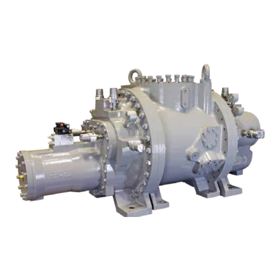
ROTARY SCREW COMPRESSOR
SBTP 4013, 4018, and 4021
THIS MANUAL CONTAINS RIGGING, ASSEMBLY, START-UP,
AND MAINTENANCE INSTRUCTIONS. READ THOROUGHLY
BEFORE BEGINNING INSTALLATION. FAILURE TO FOLLOW THESE
INSTRUCTIONS MAY RESULT IN PERSONAL INJURY OR DEATH,
DAMAGE TO THE UNIT, OR IMPROPER OPERATION.
Check www.jci.com/FRICK for the latest version of this publication.
Form 070.655-IOM (MAY 2019)
INSTALLATION - OPERATION - MAINTENANCE
File:
SERVICE MANUAL - Section 070
Replaces:
NOTHING
Dist:
3, 3a, 3b, 3c
Advertisement
Table of Contents
Troubleshooting

Related Manuals for Frick SBTP 4013


Summary of Contents for Frick SBTP 4013
- Page 1 THIS MANUAL CONTAINS RIGGING, ASSEMBLY, START-UP, AND MAINTENANCE INSTRUCTIONS. READ THOROUGHLY BEFORE BEGINNING INSTALLATION. FAILURE TO FOLLOW THESE INSTRUCTIONS MAY RESULT IN PERSONAL INJURY OR DEATH, DAMAGE TO THE UNIT, OR IMPROPER OPERATION. Check www.jci.com/FRICK for the latest version of this publication.
-
Page 2: Table Of Contents
Preparing compressor for storage ........4 MAINTENANCE Maintaining compressor ............ 5 Description ................ 5 General information ............18 FRICK 408 mm compressor .......... 5 Normal maintenance operations ........18 Compressor lubrication system ........5 General maintenance ..........18 Oil pump ............... 5 Changing oil ..............18 Recommended maintenance program ......18... -
Page 3: General Information
FROM FOREIGN AND DOMESTIC MATERIALS DESIGN LIMITATIONS FRICK 408 mm compressors are designed for operation Figure 1: Identification data plate within the pressure and temperature limits which are Rotary screw compressor serial numbers are defined by the specified by Johnson Controls-FRICK and our CoolWare ™... -
Page 4: Long Term Storage
R290, R1270, NATURAL GAS requirements and interested parties should refer to the Johnson Controls web site, www.johnsoncontrols.com/ FRICK, for specific instructions (Location: Bare Compressors\ General\Warranties\Screw Compressor Purchased for Long Term Storage). Figure 2: Refrigerant name plates The following guidelines must be followed to maintain the screw compressor warranty. -
Page 5: Maintaining Compressor
5. Provides an oil seal between the rotors to prevent rotor contact or gas bypassing. FRICK 408 MM COMPRESSOR The FRICK 408 mm rotary screw compressor utilizes mating OIL PUMP asymmetrical profile helical rotors to provide a continuous A full-time lube oil pump is required for all sleeve bearing flow of vapor and is designed for both high-pressure and compressor applications. -
Page 6: Construction Details
Rotors: The rotors are machined from AISI-1141 or Y40Mn steel to the exacting tolerances of the latest FRICK profile. The five-lobed male rotor is directly connected to the driver. The seven-lobed female rotor is driven by the male on a thin oil film. -
Page 7: Installation
Drawings for reference only can be found on pages 8 to 10. Complete dimensions and access connections can be found on the outline drawing 534E1279. If you do not have this drawing, please request it by contacting Johnson Controls- FRICK sales. - Page 8 070.655-IOM (MAY 19) SBTP 408 ROTARY SCREW COMPRESSOR Page 8 INSTALLATION COMPRESSOR PORT LOCATIONS - SBTP 408 MM ST-1 SC-5 SC-15 SM-1 SD-1 SC-9 SV-1 ST-2 SC-6 Figure 3: Compressor port locations AXIAL BEARING RTD AXIAL BEARING RTD AXIAL BEARING RTD AXIAL BEARING RTD SC-11 SC-10...
- Page 9 SBTP 408 ROTARY SCREW COMPRESSOR 070.655-IOM (MAY 19) INSTALLATION Page 9 COMPRESSOR PORT LOCATIONS - SBTP 408 MM SUCTION COMPRESSORS 4018 AND 4021 SE-2 PROXIMITY SENSOR 16” - 400# ANSI FLANGE AXIAL PROBE 1 1/4-7 UNC-2B X 2.56 DP 20X ON 22.500 B.C. COMPRESSOR 4013 12”...
- Page 10 070.655-IOM (MAY 19) SBTP 408 ROTARY SCREW COMPRESSOR Page 10 INSTALLATION COMPRESSOR PORT LOCATIONS - SBTP 408 MM VIEW D-D SL-1 SC-3 SC-2 SL-2 DISCHARGE Figure 7: Compressor port locations, view D-D...
- Page 11 Vapor injection (4018, 4021) SV-1 3-600# ANSI, 3/4-10 UNC, 1.88 DP. Vapor injection (4013) * While liquid injection oil cooling is an option for anti-friction FRICK screw compressors, it is not recommended for compressors supplied with tilting pad thrust bearings.
-
Page 12: Holding Charge And Storage
Every 408 mm compressor is pressure and leak tested at the on a wooden skid, which must be removed prior to unit Johnson Controls–FRICK factory and then thoroughly evac- installation. uated and charged with dry nitrogen to ensure its integrity during shipping and short term storage prior to installation. -
Page 13: Compressor Oil
See the next section for Johnson Controls– sure loss, gas or oil leakage and catastrophic compres- FRICK requirements. sor failure. CoolWare will select a specific FRICK oil for the refrigerant being used. Depending on the applica- COUPLING ALIGNMENT REQUIREMENTS tion, a different oil can be selected provided it is of the Coupling alignment must be performed prior to start-up. -
Page 14: Oil Cooling Requirements
CAST ALUMINUM HOUSING is important to achieve the most efficient compressor Figure 11: Capacity slide valve transmitter operation. Connect to +/- and signal as shown in the wiring diagram in Figure 10. Refer to FRICK compressor panel instructions 090.040-O for calibration procedure. -
Page 15: Directional Control Valves
Solenoids YY1, YY2, YY3 and YY4 must be wired to give the correct function. A description of their function is given in the Operation section. For control system information refer to FRICK Compressor Control Panel 090-020 O. See wiring diagram in Figure 9. Figure 13: Directional control valve wiring diagram... -
Page 16: Operation
SV solenoid YY2 is energized and oil flows from the needle valves and check valves on each port direction. This can be ordered through FRICK sales on new orders or parts unload side of the cylinder out port SC1, through valve ports A and T to compressor suction. -
Page 17: Low Ambient Operation
SBTP 408 ROTARY SCREW COMPRESSOR 070.655-IOM (MAY 19) OPERATION Page 17 SC-2 CAPACITY - LOAD (SLIDE VALVE) OIL PRESSURE OUT (INTERNAL) SC-1 SC-3 CAPACITY - UNLOAD (SLIDE VALVE) VOLUME RATIO (VI) - INCREASE (SLIDE STOP) OPTIONAL FLOW CONTROL VALVE OPTIONAL FLOW CONTROL VALVE HYDRAULIC VALVE TOP VIEW OIL PRESSURE IN... -
Page 18: Maintenance
070.655-IOM (MAY 19) SBTP 408 ROTARY SCREW COMPRESSOR Page 18 MAINTENANCE have an accumulator, and all refrigerant and oil lines MAINTENANCE should drain away from the compressor • Protect the compressor during long periods of GENERAL INFORMATION shutdown: If the compressor will be sitting for long This section provides instructions for normal maintenance, periods without running, it is advisable to evacuate to low a recommended maintenance program, and troubleshooting... -
Page 19: Oil Quality And Analysis
2. Use vibration readings taken from the new unit at start- 1. Only use FRICK oil or high quality oils approved by up as the baseline reference. Johnson Controls-FRICK for your application. -
Page 20: Capacity Linear Transmitter Replacement - Slide Valve
070.655-IOM (MAY 19) SBTP 408 ROTARY SCREW COMPRESSOR Page 20 MAINTENANCE of a problem and not causally related. The linear transmitter, with hermetic, enclosure is based on the inductive measuring principle. It features removable The third step is to identify the most likely cause and take electronics (from the sensor well) eliminating the need to action to correct the problem. -
Page 21: Troubleshooting The 408 Mm Compressor
NOTICE Unless the Service Technician has been certified by Johnson Controls–FRICK to rebuild our compressors, troubleshooting the compressor is limited to identifying the probable cause. If a mechanical problem is suspected, contact Johnson Controls–FRICK Service. Do not attempt to disassemble compressor. -
Page 22: Troubleshooting The Oil Pump And System
070.655-IOM (MAY 19) SBTP 408 ROTARY SCREW COMPRESSOR Page 22 MAINTENANCE TROUBLESHOOTING THE OIL PUMP AND SYSTEM Symptom Probable causes and corrections Pump will not produce enough Check that service valves are open. oil pressure at start-up Filter cartridges may be blocked. Check PSID across filters. Strainer may be blocked. - Page 23 SBTP 408 ROTARY SCREW COMPRESSOR 070.655-IOM (MAY 19) FORMS Page 23 DRIVE TRAIN ALIGNMENT Ambient Temperature at Time of Alignment Oil Separator Temperature at Time of Alignment Motor Coupling Type Size Distance Between Coupling Hub Faces Soft Foot Check: OK as Found Shimming Required Amount of Shims used to Correct Indicator Readings in:...
-
Page 24: Vibration Data Sheet
070.655-IOM (MAY 19) SBTP 408 ROTARY SCREW COMPRESSOR Page 24 FORMS VIBRATION DATA SHEET Date: Sales Order Number: End User: Installing Contractor: Address: Service Technician: Final Hot Alignment Equipment ID (As in Microlog): Compressor Serial Number: Face Unit Serial Number: National Board Number: Running Hours: Manufacturer and Size of Coupling:... - Page 25 SBTP 408 ROTARY SCREW COMPRESSOR 070.655-IOM (MAY 19) FORMS Page 25 Figure 19: Proximity Probes (if equipped) Compressor Drive-End Compressor Non Drive-End Male Male X and Y X and Y X ____.____ mil pk-pk X ____.____ mil pk-pk Y ____.____ mil pk-pk Y ____.____ mil pk-pk Male Axial Displacement Push-Pull...
- Page 26 070.655-IOM (MAY 19) SBTP 408 ROTARY SCREW COMPRESSOR Page 26 INDEX accumulator, 3 lifting rings, 12 allowable flange loads, 12 linear transmitter, 20 antifriction bearings, 6 load surges, 3 ASHRAE, 3 long term storage, 4 lubrication system, 5 bare compressor, 20 booster, 16 maintenance, 18 maintenance...
- Page 27 SBTP 408 ROTARY SCREW COMPRESSOR 070.655-IOM (MAY 19) INDEX Page 27 slide valve, 5, 6, 14, 19 slide valve transmitter, 14 solenoids, 15 solenoid valves, 16 start-up, 17 storage, 12 suction accumulator, 18 suction line, 3 suction pressure, 19 suction strainer, 17, 18 system piping, 19 thermal stability, 6 transmitter unit, 20...
- Page 28 JOHNSON CONTROLS Supersedes: NOTHING 100 Cumberland Valley Avenue Subject to change without notice Waynesboro, PA 17268-1206 USA Published in USA • 05/19 • PDF Phone: 717-762-2121 • FAX: 717-762-8624 www.jci.com/FRICK © 2019 Johnson Controls Int’l PLC - ALL RIGHTS RESERVED...
Need help?
Do you have a question about the SBTP 4013 and is the answer not in the manual?
Questions and answers