
Related Manuals for Ryobi Homelite RY48ZTR75/100


Summary of Contents for Ryobi Homelite RY48ZTR75/100
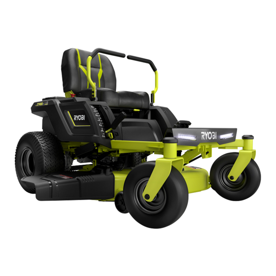
- Page 1 Ryobi RY48ZTR75/100 Riding Mower Electrical Components Troubleshooting and Testing J.Davis 4-18-2019 Anderson, South Carolina...
- Page 2 Table of Contents WARNING • Testing Headlight Assembly • ZTR Mower Overview • Testing Accelerator (angular transducers) • Brushless Motors Testing Brake Switch • • Using this Manual Testing Beeper • • Testing Seat Switch ZTR Block Diagram and Control Flow •...
- Page 3 THIS MATERIAL INTENDED ONLY FOR TECHNICIANS TRAINED IN ELECTRICITY. Technicians should wear personal protective equipment, such as rubber gloves and safety glasses Exercise caution at all times Dangerous voltages /currents are present. This manual assumes knowledge of basic electrical equipment such as DMM (Digital Multi Meter) to measure voltage, current, resistance, continuity, and diodes.
- Page 4 ZTR Mower Overview The Ryobi ZTR riding mower is completely electrical, consisting of 4 brushless motors and a controller for each motor for each motor: • A brushless motor and controller for each of the 2 blades • A brushless motor/controller to drive each rear wheel. These...
- Page 5 Brushless Motors Brushless motors operate quite differently than brushed motors, which you may be used to (i.e. a starter motor). A brushed motor can be quickly tested by applying voltage to the two terminals. Brushless motors can be recognized by wires.
-
Page 6: Using This Document
Using this Document • Any blue text can be clicked on to jump directly to the page of that topic. (This document is also printer-friendly, so you can have it in front of you while servicing the mower.) If you print this document, we recommend printing it in landscape mode and in color •... - Page 7 ZTR Block Diagram And Control Flow Left RIGHT 5V out Head Batteries Neutral Neutral Lights switch switch Main Fuse Accelerator Accelerator Charge Port/lockout/ Drive Speed battery temp Switch Seat 48V to 12V Relay switch (DC to DC) Fuse Brake converter Switch Switch Enable...
-
Page 8: Troubleshooting: General
Troubleshooting: General • Follow the Block Diagram on the previous page. • Check for loose/bad connections. • Test the easiest components first. (power, key switch, DC-DC converter) • Mower should be fully charged (if possible) • Before disassembly: – Attempt to charge mower (note any error LED indications) –... - Page 9 Troubleshooting: Detailed Use the block diagram as a guide Also refer to the beep diagnostic code chart 1. Verify the battery charger is functional by plugging it into the charge port on the back of the mower and let the mower fully charge. 2.
-
Page 10: Digital Multi Meter (Dmm)
Digital Multi Meter (DMM) Typical DMM (Fluke 87). Note the dial is set to the “DIODE” function. this function will be used in many of the following procedures. Also note where the and black jacks of the test leads are connected to the DMM. If you are unfamiliar with a DMM, please read the section Electronics Tips for the Mechanical Small Engine Technician <... - Page 11 Other Helpful Tools and Parts 12V output 5V output < Table of Contents...
-
Page 12: Component Locations
Component Locations Seat Switch Charge port Beeper Access panel Controllers (under seat) DC-DC Brake Switch converter Headlights Neutral “zero” Switches Accelerator transducers < Table of Contents... - Page 13 Controllers and Label Locations (Shown with passenger leg panel removed) “Deck Motor Controller” “Drive Motor Controller 2” “Drive Motor Controller” < Table of Contents...
- Page 14 Main Battery Connection Main battery disconnect is located directly under the seat access cover. It may takes considerable pressure to separate the halves. If you can not separate by hand, you may need a blunt instrument to push in the hole in the direction indicated. Note that one half of the connector is screwed to the frame and will not move.
- Page 15 Testing Main Fuse IMPORTANT: If the main fuse is blown, find the source of problem before replacing fuse 1. Disconnect main battery connection 2. Open the plastic box to access main fuse. 3. Set DMM to Resistance Measure where indicated below. Ensure the nuts are tight, but not overtightened, as this can cause the fuse to twist and break.
-
Page 16: Testing Battery Voltage
Testing Battery Voltage 1. Set DMM to “DC Volt” mode. 2. Turn mower on. 3. Pull PTO switch up (Power Take Off/Blade Engage knob) to load the battery for more accurate measurement. 4. Place DMM probes indicated by red arrow, BLACK probe by black arrow Charge Indicator LED Charger Interlock Note: If a valid voltage... -
Page 17: Control Panel
Control Panel Power Switch Blade power Switch (AKA “PTO” Switch Headlights Low/High Blade Cutting Speed Low/HighDrive Speed Fuel Gauge USB Charge Port < Table of Contents... - Page 18 Testing PTO (Power Take Off) Switch 1. Mower Power OFF Note: Make sure 2. DMM set to measure spade lugs are Resistance secure. They should be locked in place and should not come loose if the wires are 3. Insert DMM probes where indicated. pulled on.
- Page 19 Testing Headlight Switch 1. Disconnect Main Power from Mower. 2. DMM set to “Diode” mode. Touch leads where indicated. LED should light (polarity of probes does not matter). Set DMM to Resistance mode This is a latching switch. Pressing the button alternates between open and closed switch.
- Page 20 Testing Drive Speed Switch and Cutting Speed switch • This test procedure is the same as the headlight switch procedure. The only difference is these switches are momentary. • When the button is held in, the switch is closed. • When the button is released, the switch is open. <...
- Page 21 Testing Fuel Gauge / Hour Meter Percent Charge remaining Approximate charge remaining Total hours of use (mower must be on Continuously for a minimum Turn Mower switch ON. of 6 minutes for time to change) Set Volt meter to “DC VOLTS”. and black wire (below, left) Measure battery voltage between Measure battery voltage between black and...
- Page 22 Testing Key Switch 1. Set DMM to DC Volts 2. With Power switch OFF, measure battery voltage where indicated 3. With Power ON, measure approx. 0V where indicated 48V DC Note this switch operates at To measure Switch with wires disconnected: 1.
- Page 23 Testing USB Port 1. Power ON Mower. 2. Set DMM to measure DC Volts. 3. Connect a scrap USB cord with one end removed. 4. Measure 5V between the red and black wire USB power indicator LED* Measure 12V where indicated below. If LED indicator is not on, USB port is bad.
- Page 24 Testing the Zero Switches A zero switch is located at the base of each steering arm < Table of Contents...
- Page 25 Testing the Neutral Switches Set meter to measure continuity and connect probes With switch NOT pressed, measure no continuity With switch pressed, measure continuity Make sure wires and connector are in good shape and wires don’t pull loose Note: the switches are pressed when the steering arms are in the out position <...
- Page 26 Testing Head Light Assembly POSITIVE ”+” “-” NEGATIVE To test Headlight module independently: 1. Power on Mower. 2. Turn on Headlights. 1. Disconnect Headlight from wire harness. 3. Set DMM to measure DC Volts. 2. Supply 12V to the connector as shown above. 4.
- Page 27 Testing Angular Transducer (Accelerator) Test for Voltage at Harness 1. Set DMM to measure DC Volts. 2. Disconnect Accelerator connector. 3. Turn mower on. 4. Measure 4-5V between red and black wires on harness. 4.25V typical To Test Transducer Independently: 1.
- Page 28 Testing Brake Switch 1. Set DMM to measure DC Volts. 2. Disconnect brake switch connector. 3. Measure DC Volts between red and black terminals on the mating connector of the harness 3.2V nominal when plunger depressed To test brake switch independently: Power Off Mower.
- Page 29 Testing the Beeper To Test out of circuit: Disconnect from harness and connecting 12V “+” to red wire and “-” to black ground wire of beeper. You Should hear a beep To test on the mower: With power on, remove yourself from the seat. Please note: it may take up to 1 minute for beeper To activate To measure the voltage at the harness:...
- Page 30 Testing Seat Switch Seat Switch is Normally Open (N.O.) when no pressure is applied to seat 1. Power Mower OFF. 2. Set DMM to measure Resistance. 3. Disconnect seat switch connectors. 4. Measure continuity when switch is pressed. 5. Measure very high resistance when switch is released. 0-.2 Ohms nominal when pressed To Measure the harness: 1.
- Page 31 Testing Master and Slave Blade Controllers Test for short circuit: 1. Disconnect all connectors to Master Controller. 2. Temporarily touch a wire between heavy red “+” and heavy black “-” wires to drain capacitance. 3. Set DMM to Resistance Mode. 4.
- Page 32 Testing Drive Motor Controllers Master Drive Controller Slave Drive Controller • Make sure all wires from the controller are disconnected from the Mower. • Connect a jumper wire from the ground wire to each of the other wires to drain capacitance Test for short circuit: 1.
- Page 33 Testing Master and Slave Blade Motors ***IMPORTANT*** IGNORE the 1. Disconnect Motor from controller. “N”, “L” and “G” labels on the 2. Set DMM to Resistance mode. connector. These are NOT for 3. Measure between any 2 pins. “Neutral”, “Line” and “Ground” 4.
- Page 34 Test Drive Motors 1. Unbolt heavy phase wires from drive controller 2. Set DMM to Resistance mode 3. Measure resistance between heavy green and heavy yellow wire on motor 3 Measure resistance between heavy green and heavy blue wire on motor. 4.
- Page 35 Testing Drive Motor Hall Sensors (in Mower) Note: power should be ON and rear end raised so wheels can turn without mower moving Set DMM to “DC Volts” 1. connect red probe to red wire (power). 2. Black probe to black wire (ground). 3.
- Page 36 Testing Drive Motor Hall Sensors (Independently) 1. Turn OFF mower. 2. Disconnect all wires from motor to mower. 3. Apply 5V (red to red, black to black). Note: a scrap USB cord and USB cell phone charger can be used to supply 5V Repeat measurements from previous page, while turning the motor by hand.
- Page 37 Testing 48V-to-12V (DC-DC) Converter Testing Converter Fuse: 1. DISCONNECT MAIN POWER. 2. Check continuity of fuse (see next page) 3. If fuse is bad, replace only with same type and Amperage (12V, 2A automotive fuse) Testing Converter: 48V-to-12V converter module 1.
- Page 38 Testing DC-DC converter Fuse To test the DC-to-DC converter fuse • remove the rubber cap • Test continuity where indicated • If fuse is bad, replace only with same fuse value < Table of Contents...
- Page 39 Testing Relay 1. Power Mower ON. 2. Set DMM to “DC Volts”. 3. Check for 12V on the small terminals (under the black caps). 4. Check for approximately 39+V on the large terminals (under the red caps). Alternate method to test relay independent of mower: 1.
- Page 40 Testing Relay Diode Diode Test: Turn Mower OFF. 2. Unbolt one leg of diode and disconnect from the circuit. Diode 3. Set DMM to “Diode”. 4. Connect lead at arrow, black lead at black arrow. DMM should read approx .7V. 5.
- Page 41 Testing the Charge Port and Interlock 1. Turn mower on. Jumper wire with Banana plugs (available at 2. Turn headlights on. mouser.com Use extreme caution the jumper is in the Correct sockets, otherwise a short circuit May result in step 3. 3.
- Page 42 Testing the Battery Charger Note: There are no electronics needed for this test. But you will need suitable 12 gauge wires Use caution especially as shown. This procedure will charge the batteries (if the charger and batteries are good). If using alligator clip jumper wires. Wear rubber gloves and eye protection. Refer to photos on next page for this procedure Disconnect main battery connection.
- Page 43 Testing the Battery Charger Alligator clips BLACK CLIPS Charger indicator Refer to “Charger Error Codes” CLIP Close up of 12 AWG wire connector Alligator clips RED “+” BLACK “-” Test clips CONNECT MAIN POWER LAST CONNECT MAIN POWER LAST Testing the battery charger using commonly available alligator clips/jumper wires. <...
- Page 44 Battery Charger Error Codes < Table of Contents...
- Page 45 ZTR Beep Diagnostic Codes Beep # Description check: if not solved… if not solved… if not solved… angle sensor turn key off, return both levers to open, replace control lever Replace charger board check angle sensor connections turn key on assembly not at neutral return both levers to open and try...
-
Page 46: Testing The Temperature Sensor
Testing the Temperature Sensor Disconnect the plastic connector • Set DMM to measure RESISTANCE. • At room temperature, measurement should be approximately 10K Ohms. • As the sensor is heated, the resistance will decrease. • If sensor is bad or has broken connection, the charger will blink an error code. -
Page 47: Wire Harness Diagram
Wire Harness Diagram < Table of Contents... - Page 48 Pre and Post Repair Checklist Set Parking brake. Jack rear tires approximately 2” off the ground and support securely with jack stands. Sit on mower. Release the brake. Turn main power key to “ON”. The Fuel Gauge/Hour meter should light up. Push handles fully forward and hold.
- Page 49 Electronics Tips for the Mechanical Small Engine Tech A service person who has spent many years working on gas mowers may feel uneasy when working on the new generation of electric mower. If this sounds like you, fear not, you’re not alone. This section is for you. Keep in mind you were born with the most powerful trouble shooting tools: Eyes: LOOK for signs of wear, deformation, disconnection, pinched wires, charger LED patterns...
- Page 50 Electronic Terms, Symbols, and Tools Voltage is potential Energy noted by the symbol “V”. For the scope of this document we are only concerned With DC voltage. So be sure when setting the DMM to Measure voltage it is set to DC. Resistance is opposition to the flow of current.
- Page 51 Using The DMM to measure Volts Before touching the probes of a DMM to Anything, be sure DMM it is set to the correct Setting and probes are inserted into the correct jacks To measure DC voltage: 1. first set the DMM to measure voltage, ensuring DC (NOT AC) setting 2.
- Page 52 Using the DMM to Measure Resistance Before touching the probes of a DMM to anything, be sure it is set to the correct setting. Power must be OFF when measuring resistance To measure DC voltage: 1. First, set the DMM to measure resistance 2.
-
Page 53: Revision Log
Revision Log 9-21-2018 Modeled after the Ryobi Riding Tractor Repair manual. 10-12-2018 Added Beep Diagnostic Codes 2-04-2019 Several clarifications based on initial feedback 2-20-2019 added source for 125A 58V main fuse at Mouser.com https://www.mouser.com/ProductDetail/Littelfuse/14256316122?qs=sGAEpiMZZMsh2y49K8ANrTdpOrToc%252bEOWEps5yIgKK0%3d 4-18-2019 - Added extended beep code chart...
Need help?
Do you have a question about the Homelite RY48ZTR75/100 and is the answer not in the manual?
Questions and answers
both blade motor controllers smoked after replacing batteries with lifepo4 batteries. are there any ways to fix this and still use lifepo4 batteries
To fix the blade motor controllers on a Ryobi Homelite RY48ZTR75/100 after they smoked from using LiFePO4 batteries:
1. Check Fuse: If a fuse is blown, replace it with the same physical size, Amperage, and Voltage rating.
2. Inspect Wiring and Connectors: Check for loose or bad connections, especially around the blade motor controllers and related wiring.
3. Test Components: Use a Digital Multi Meter (DMM) to test power, key switch, and DC-DC converter. Ensure the mower is fully charged if possible.
4. Controller Communication: Blade motor controllers have a master-slave setup. If one controller fails, both shut down. Replace the damaged controller(s) as needed.
5. Use Correct Battery: Ensure the battery used is compatible with the system’s voltage and current specifications. LiFePO4 batteries may not be suitable if they caused damage.
6. Disassembly and Inspection: Remove the instrument panel cover to access and inspect the key switch and other connections.
If the controllers are visibly damaged or not functioning after checking these steps, they likely need replacement.
This answer is automatically generated