
Subscribe to Our Youtube Channel
Related Manuals for Tektronix TYPE CA


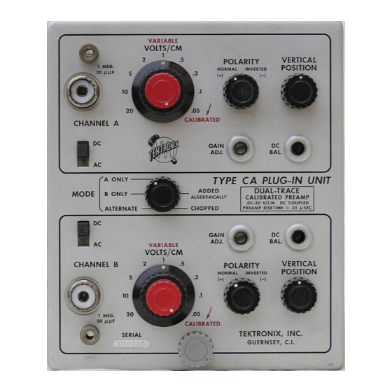
Summary of Contents for Tektronix TYPE CA
- Page 1 NSTRUCT ON ANUAL ekfronix, Inc. .W. Millikan Way • P. O. Box 500 • Beaverton, Oregon • Phone Ml 4-0161 • Cables: Tektronix ekfronix International A.G. Terrassenweg 1A • Zug, witzerland • PH. 042-49192 • Cable: Tekintag, Zug witzerland •...
-
Page 2: Warranty
WARRANTY All Tektronix instruments are warranted against defective materials and workman ship for one year. Tektronix transformers, manufactured in our own plant, are war ranted for the life of the instrument. Any questions with respect to the war ... - Page 3 Type CA http://manoman.sqhill.com...
- Page 4 CONTENTS Warranty ection 1 Characteristics ection 2 Operating Instructions ection 3 Circuit Description ection 4 Maintenance ection 5 Calibration ection 6 Accessories ection 7 Parts List and chematic Diagrams Type CA ht+ p7/manoman.sqhill.com...
- Page 5 Because GENERAL the sweeps are identical, and time-delay char The Type CA Unit contains two identical acteristics of the two amplifier channels are closely controlled, time comparisons accurate amplifier channels that can be electronically switched either by the oscilloscope sweep or at within 1 nsec can be made.
- Page 6 (A +or- B) Weight--4 1/2 lbs. Amplifier Sensitivity Basic deflection factor--.05 v/cm, ac or dc. Accessories Nine calibrated sensitivities--. 05 v/cm to 20 v/cm, accurate within 3% when set on any one 2-Instruction Manuals. step. Characteristics - Type CA...
- Page 7 OPERATING INSTRUCTIONS Plug the unit into a Tektronix convertible imately 100 kc so that each channel conducts Oscilloscope and turn the power on. Allow for about 5 μ sec and then is cut off while the the instrument to reach operating temperature, other channel conducts for an equal time.
- Page 8 Type CA. The their shape, relative amplitudes, etc. POLARITY switch has two positions. In the...
- Page 9 Fig. 2 I. Functions of the Type CA front panel controls Operating Instructions - Type CA http://manoman.sqhill.com...
- Page 10 The Algebraic Output The problem here is to be able to observe of the Type CA unit (with the MODE switch the transient using both amplifiers during a the ADDED ALGEBRAICALLY position) single sweep cycle.
- Page 11 PLIFIERS varied over about a 2 1/2 to 1 range. The Type CA Plug-In Unit consists of two The GAIN ADJ control permits the basic identical amplifier channels and a channel ...
- Page 12 V4383. In phase input signals add, out of phase input signals subtract, at the grid of CHOPPED each tube if the polarity switches are at the same setting. Turning the MODE switch to the CHOPPED Circuit Description - Type CA...
- Page 13 Calibration followed or if certain precautions are taken. Additional information for the replacement of The Type CA Plug-In Unit is designed for maximum stability and should not require fre some of these parts is contained in the following paragraphs.
- Page 14 4. Apply only one corner of the tip to the If you are responsible for the maintenance of a large number of Tektronix instruments, or if you contemplate frequent parts changes, we recommend that you keep on hand a stock of solder containing about 3% silver.
- Page 15 (see Fig. 4-6) makes a convenient tool for this purpose. Ceramic Strips Two distinct types of ceramic strips have been used in Tektronix instruments. The earlier type mounted on the chassis by means of Fig. 4-7. Two types of ceramic strip mountings. Maintenance - Type CA...
- Page 16 To replace strips which mount with snap-in Color Coding plastic fittings, first remove the original All wiring in the Type CA Unit is color fittings from the chassis. Assemble the mount coded to facilitate circuit tracing. pecific ing post on the ceramic strip. Insert the...
-
Page 17: Calibration Procedure
If you suspect that the unit is out of cal the op ration of the Type CA Plug-In U t. In tion, this section may be used to isolate ibration but you are not aware of which par ... - Page 18 Fig. 5-1. pecial Dual-Input coax connector. Install the Type CA Unit in the oscilloscope. 12. Miscellaneous alignment tools. ee Fig. Turn on all the test equipment and allow 15 minutes for it to warm up. et the oscillo ...
- Page 19 .1 VOLT 5. Checking POLARITY Switch CALIBRATOR With the MODE switch in ALTERNATE et the Type CA as follows: position the traces to the center of the CRT. MODE ALTERNATE switch the POLARITY switches from NORMAL to INVERTED. The traces should VOLT /CM ( A and B) not shift more than one centimeter.
- Page 20 POLARITY switch to INVERTED. The two signals should now cancel each other out within P52 cable and the Type CA Unit with the 5XT 1 cm. You may adjust the VERTICAL PO ITION between the P52 cable and the capacitance standardizer.
- Page 21 MODE switch of the Type CA Unit the 5XT directly to A channel input connector. to A ONLY and connect the Type 107, in the When the adjustments to A channel have been same manner as above, to the A channel completed connect the cable from the Type vertical input connector.
- Page 22 AC and check to see that you have cancel Turn the MODE switch to ADDED ALGEBRAI lation of the signal within one centimeter. Fig. 5-3. Left side view of Type CA Unit showing iocation of adjuatmenti*. Calibration - Type CA http://manoman.sqhill.com...
- Page 23 X000 Part first odded ot this serial number 000X Part removed ofter this serial number. *000-000 Asterisk, preceding Tektronix Part Number indicates rrianufactured by or for Tek tronix, also reworked or checked components. (Mod. w/) Simple replacement not recommended.
-
Page 24: How To Order Parts
HOW TO ORDER PARTS Replacement parts are available through your local Tek- tronix Field Office. Improvements in Tektronix instruments are incorporated as soon as available. Therefore, when ordering a replacement part it is important to supply the part number including any suffix, instrument type, serial number, plus a modification number where applicable. - Page 25 Cer. 500 v 281-524 150 μμf C4310C 500 v 281-027 .7-3 μμf Tub. Var. C4311B 500 v 281-027 .7-3 μμf Tub. Var. C4311C t Added where needed. ft These Capacitors are selected during calibration. PART LI T — TYPE CA...
- Page 26 L3334 L3354 *114-043 .5-1 μh Var. core 276-506 L3360 *108-072 .75 μh *108-072 L3361 .75 μh *114-051 Var. core 276-506 L3362 .9-1.6 μh †† These Capacitors are selected during calibration, † Added where needed. PART LI T — TYPE CA...
- Page 27 R3320 1 meg ½ W R3321 302-105 101-14520 1 meg ½ W 316-105 1 meg 14521 -up ¼ W 47 Ω R3322 302-470 101-14520 ½ W 47 Ω ¼ W 316-470 14521 -up PARTS L ST — TYPE CA http://manoman.sqhill.com...
- Page 28 ½ W 302-470 47 Ω 101-14320 R4310E 47 Ω 316-470 14321 -up ¼ W 309-003 500 k Prec. R4311C ½ W Ω R4311D 302-470 X25730-up ½ W Prec. R4311E 309-014 1 meg ½ W PART LI T — TYPE CA...
- Page 29 ½ W 302-104 100 k R4375 ½ W Vert. Pos. & Range 2 x 100 k 311-051 R4376 302-104 100 k R4377 ½ W R4382 304-182 1.8k 303-822 8.2 k R4383 303-822 8.2 k R4384 PART LI T — TYPE CA...
- Page 30 V3375 154-039 V3382 154-016 6AL5 154-039 12AT7 V3384 154-039 12AT7 V3393 V4323 154-014 6AK5 154-040 12AU6 V4334 V4354 154-040 12AU6 V4364 elected pair. Furnished as a unit. Use *157-059 6AU6 V4374 154-039 12AT7 V4383 PART LI T — TYPE CA...
- Page 31 510-502 LUG, OLDER, 510-22/ NUT, HEX, 2-^- x 210-40/ NUT, HLX, 4-40x 3 / 16 510-406 NUT, HLX, 6-32 x >/„ 210-40/ NUT, HLX, 8-35 x 'm 510-409 210-41/ NUT, HLX, %-32 x V PART LI T — TYPE CA...
- Page 32 PACER, NYLON, 3/ u , FOR CERAMIC TRIP 361-008 PACER, NYLON, 3 /,x, FOR CERAMIC TRIP 361-009 TRIP, CERAMIC, 3 / 4 4 NOTCHE , CLIP MTD. 124-088 TRIP, CERAMIC, % x 9 NOTCHE , CLIP MTD. 124-090 PART LI T — TYPE CA...
- Page 33 WA HER, FIBER, #10 210-812 WA HER, TEEL, .390 x x .020 210-840 WA HER, TEEL, .093 x ’ / 32 x .020 210-850 WA HER, RED FIBER, % x ,34 x .035 210-906 PART LI T — TYPE CA...
- Page 34 CHANNEL A PARTS SHOWN WITHOUT VALUES ARE SEE PARTS LIST FOR EARLIER SELECTED COMPONENTS. 10- 5 -si VALUES AND S/N CHANGES OF PARTS LIST. PARTS ARRED WITH RED TINT BLOCRS TYPE CA ATTENUATION NETWORKS...
- Page 35 R4311E TYPE CA VOLTS/CM "B ” BOTTOM VIEW...
- Page 36 20,000 Ω/V VOM. ALL READINGS ARE IN VOLTS. parts marked with red TYPE CA PREAMPLIFIER tint blocks VOLTAGE AMPLITUDE MEASUREMENTS, AS SHOWN, ARE NOT ABSOLUTE. THEY MAY VARY BETWEEN INSTRUMENTS AS WELL AS WITHIN THE INSTRUMENT ITSELF DUE TO NORMAL MANUFACTURING TOLERANCES, AND TRANSISTOR AND VACUUM TUBE CHARACTERISTICS.
Need help?
Do you have a question about the TYPE CA and is the answer not in the manual?
Questions and answers