Sign In
Upload
Download
Table of Contents
Contents
Add to my manuals
Delete from my manuals
Share
URL of this page:
HTML Link:
Bookmark this page
Add
Manual will be automatically added to "My Manuals"
Print this page
×
Bookmark added
×
Added to my manuals
Manuals
Brands
Tektronix Manuals
Amplifier
TCP300 Series
User manual
Tektronix TCP300 Series User Manual
Amplifiers & ac/dc current probes
Hide thumbs
1
2
3
4
5
6
Table Of Contents
7
8
9
10
11
12
13
14
15
16
17
18
19
20
21
22
23
24
25
26
27
28
29
30
31
32
33
34
35
36
37
38
39
40
41
42
43
44
45
46
47
48
49
50
51
52
53
54
55
56
57
58
59
60
61
62
63
64
65
66
67
68
69
70
71
72
73
74
75
76
77
78
79
80
page
of
80
Go
/
80
Contents
Table of Contents
Troubleshooting
Bookmarks
Table of Contents
Table of Contents
General Safety Summary
Compliance Information
EMC Compliance
Environmental Considerations
Preface
Manual Conventions
Getting Started
Figure 1: Typical TCPA300/400 Current Measurement System
System Configuration
Options
Table 1: Amplifier Options
Table 2: Service Options
Optional Accessories
Standard Accessories
Figure 2: Using the Probe Covers
Probe Covers
Figure 3: Equipment Locations in the Travel Case
Travel Case
Connecting the Amplifier to an Oscilloscope
Power on the Amplifier
Connecting a Current Probe to the Amplifier
Figure 4: Connecting and Disconnecting a Current Probe to the Amplifier
Figure 5: TCP312 and TCP305 Slide Operation
Operating the Current Probe Slide
Figure 6: Unlock and Open the TCP303 and TCP404XL
Figure 7: Close and Lock the TCP303 and TCP404XL
Degaussing and Autobalancing the Current Probe
DC Measurements
Figure 8: Current Probe Polarity
AC Measurements
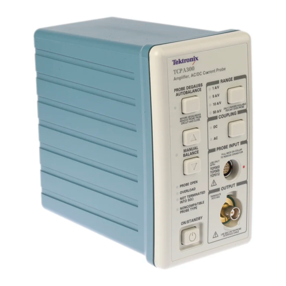
Figure 9: the TCPA300 Front Panel
TCPA300 and TCPA400 Controls
Control Summary
Reference Notes
Degaussing a Probe with an Unpowered Conductor in the Jaws
Table 3: Unpowered Circuit Degauss Limits
Measuring Differential Current
Figure 10: Measuring Two Conductors
Figure 11: Measuring Differential Current and Nulls
AC and DC Coupling
Figure 12: Effect of AC or DC Coupling on Low-Frequency Signals
Maximum Current Limits
Figure 13: Applying the Amp-Second Product Rule
Measuring Noncontinuous Current with the TCP404XL Probe
Figure 14: Duty Cycle Calculation
Extending Current Range
Figure 15: Adding a Second Conductor
Figure 16: Adding Multiple Turns
Increasing Sensitivity
Figure 17: Increasing Probe Sensitivity
Application Notes
Automobile Charging Systems
Table 4: Automobile Charging Systems Test Setup
Figure 18: Setup for Measuring Charging Current
Figure 19: Charge Current Waveforms
Figure 20: Measuring Inductance with a Low-Impedance Source
Inductance Measurements
Figure 21: Linear Current Vs. Time Ramp
Continuity Test of Multiple-Conductor Cable
Figure 22: High-Impedance Source Current Ramp
Figure 23: Measuring the Number of Turns in a Coil
Figure 24: Turns Measurement Using Reference Coil
Measuring Inductor Turns Count
Power Measurement and Analysis Software
Table 5: Troubleshooting
Displaying Error Codes with the Probe Degauss Autobalance Button
Figure 25: Error Code Display
Figure 26: Interpreting the Error Code Display
Table 6: Amplifier Error Codes
Correcting the Cause of an Error Code
Shutdown Error
Troubleshooting and Error Codes
Specifications
Warranted Specifications
Table 7: Warranted TCPA300 and TCPA400 Specifications
Nominal and Typical Characteristics
Table 8: Nominal and Typical Amplifier Characteristics
Mechanical Characteristics
Table 9: TCPA300 and TCPA400 Mechanical Characteristics
Figure 27: Probe Jaw Dimensions (Nominal)
Table 10: Probe Mechanical Characteristics
Table 11: Shipping Weights and Dimensions
Environmental Characteristics
Table 12: Environmental Characteristics
Performance Graphs
Figure 28: Frequency Derating-TCP312
Figure 29: Frequency Derating-TCP305
Figure 30: Frequency Derating-TCP303
Figure 31: Frequency Derating-TCP404XL
Figure 32: Insertion Impedance Versus Frequency
Figure 33: Specified Operating Area of the Probes
TCP404XL Maximum Measurement Times
Figure 34: Measuring 750A Noncontinuous at 50 °C Ambient Temperature
Figure 35: Measuring 600A Noncontinuous at 50 °C Ambient Temperature
Safety Compliance Information
Figure 36: Measuring 750A Noncontinuous at 23 °C Ambient Temperature
Table 13: Safety Compliance Information
Glossary
Advertisement
Quick Links
Download this manual
xx
TCPA300/400 Amplifiers &
TCP300/400 Series AC/DC Current Probes
ZZZ
User Manual
*P077118300*
077-1183-00
Table of
Contents
Previous
Page
Next
Page
1
2
3
4
5
Advertisement
Table of Contents
Need help?
Do you have a question about the TCP300 Series and is the answer not in the manual?
Ask a question
Questions and answers
Related Manuals for Tektronix TCP300 Series
Amplifier Tektronix TCPA300 SERIES Instruction Manual
Amplifiers & ac/dc current probes (205 pages)
Measuring Instruments Tektronix TCP305 Service Manual
Tcpa300 series; tcpa400 series ac/dc current probes (120 pages)
Measuring Instruments Tektronix TCP312 Service Manual
Tcpa300 series; tcpa400 series ac/dc current probes (120 pages)
Amplifier Tektronix TCPA300 User Manual
Series ac/dc current probes (82 pages)
Amplifier Tektronix TCPA300 Safety Instructions
Amplifiers and current probes (32 pages)
Amplifier Tektronix TCP404XL Safety Instructions
Amplifiers and current probes (32 pages)
Amplifier Tektronix TekConnect TCA-1MEG Specifications
High-impedance buffer amplifier system (4 pages)
Amplifier Tektronix TPA-N-PRE Instructions Manual
Preamplifier for the mdo4000 series (7 pages)
Amplifier Tektronix TCP305A Safety Instructions
Amplifiers and current probes (32 pages)
Amplifier Tektronix TCP312A Safety Instructions
Amplifiers and current probes (32 pages)
Amplifier Tektronix TCP400 Series User Manual
Amplifiers & ac/dc current probes (80 pages)
Amplifier Tektronix 7A26 Instruction Manual
Dual trace amplifier (69 pages)
Amplifier Tektronix 7A18 Instruction Manual
Dual trace amplifier (103 pages)
Amplifier Tektronix 11A52 Manual
Two channel amplifier (50 pages)
Amplifier Tektronix 11A34 Service Reference Manual
Four-channel amplifier (54 pages)
Amplifier Tektronix 7A26 Instruction Manual
Dual trace amplifier (88 pages)
This manual is also suitable for:
Tcp400 series
Tcpa300
Tcpa400
Tcp312
Tcp305
Tcp303
...
Show all
Tcp404xl
Table of Contents
Print
Rename the bookmark
Delete bookmark?
Delete from my manuals?
Login
Sign In
OR
Sign in with Facebook
Sign in with Google
Upload manual
Upload from disk
Upload from URL


Need help?
Do you have a question about the TCP300 Series and is the answer not in the manual?
Questions and answers