
Related Manuals for Tektronix Type Z


Summary of Contents for Tektronix Type Z
- Page 1 NSTRUCT ON MANUAL ektronix, Inc. .W. Millikan Way • P. O. Box 500 • Beaverton, Oregon • Phone Ml 4-0161 • Cables.- Tektronix ektronix International A.G. Terrassenweg 1A • Zug, witzerland • PH. 042-49192 • Cable: Tekintag, Zug witzerland •...
-
Page 2: Warranty
WARRANTY All Tektronix instruments are warranted against defective materials and workman ship for one year. Tektronix transformers, manufactured in our own plant, are war ranted for the life of the instrument. Any questions with respect to the war ... - Page 3 CONTENTS Warranty pecifications ection 1 Operating Instructions ection 2 Circuit Description ection 3 Maintenance ection 4 Calibration ection 5 Accessories ection 6 Parts List and Diagrams ection 7 Type Z ://manoman...
- Page 4 Type Z...
- Page 5 Vertical Deflection Factors 0.05 to 25 volts per centimeter in nine calibrated steps; The Type Z Plug-In Unit is a calibrated differential com also continuously variable (uncalibr a ted) between steps and parator preamplifier designed for use in all Tektronix up to 60 volts per centimeter.
- Page 6 Specifications — Type Z Comparison Voltage Accuracy Measurement Resolution Resolution accuracy, at 100-volts comparison voltage — Within 5 millivolts [0.5%) on the ±l-volt range. 0.005% Within 20 millivolts (0.2%) on the ±10-volt range. Maximum resolution — 5 millivolts per millimeter.
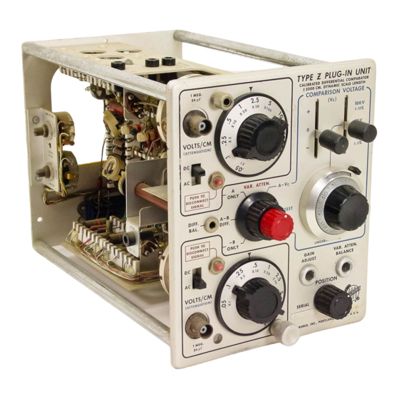
- Page 7 (that is, to obtain a straight- line appearance of the trace). A front-panel view of the Type Z Unit is shown in Fig. 2-1. 3. Variable Attenuator Balance In addition, a brief functional description is given of the Any vertical shift of the oscilloscope trace when the VAR.
- Page 8 Operating instructions — Type Z VAR. ATTEN. — Varies the verti Polarity — Selects compar cal deflection factors between ison voltage polarity. ranges of the VOLTS/CM con trols. VOLTS/CM — Selects the verti Mode — Selects operating cal deflection factors.
- Page 9 Operating nstructions — Type Z Conventional Preamplifier Operation When the Z Unit is used for conventional preamplifier operation, the Mode switch should be placed in either the A ONLY or the — B ONLY position. Input signals should then be connected to the corresponding input connector.
- Page 10 Operating nstructions — Type Z matching between A and B input circuits is necessary, one Differential operation between the two inputs is obtained input d c blocking capacitor may be “ padded" with a small when the Mode switch is in the A-B DIFF. position. Maximum additional capacitance, generally less than 0.001 /ifd.
- Page 11 Operating nstructions — Type Z form could be seen but not easily measured. With a 5. Either input signal alone may be viewed without switch common-mode rejection of 40,000 to 1, the hum would be ing back to the A ONLY or — B ONLY positions of the reduced to 0.5 mm and the desired signal alone could be...
- Page 12 Operating nstructions — Type Z 1. DC Voltage Measurements. (c) The voltage difference between the two points is read from the Helidial and the setting of the Range switch. When the Z Unit is used to make any d c voltage measure ...
- Page 13 Operating instructions — Type Z Checking Attenuation Accuracy of VOLTS/CM divider resistor R1 is the 1-meg input resistor in the oscil loscope, R2 is the resistor in the probe. The procedure which Switches follows describes a method for checking a 10X attenuator probe.
- Page 15 DESCR PT ON BLOCK D AGRAM DESCR PT ON DETA LED C RCU T DESCR PT ON Fig. 3-1 shows the block diagram for the Type Z Unit. Comparison Voltage Regulator ignals applied to A Input and B Input connectors pass through the VOLT /CM Attenuator switches to the grids Regulation of both the + and —...
- Page 16 The signals are then impressed upon the grids of the input cathode followers, V7613 and V8613. The wide dynamic range of the Type Z Unit requires constant-current operation of both the Input Cathode Fol lower stage and the Differential Amplifier stage. Another requirement is that screen-to-cathode voltages remain con ...
- Page 17 Circuit Description — Type Z sistor, Q8672. The bias of V7618A is the collector-to-base As in the Input Cathode Follower stage, the screen volt voltage of Q7618 plus the drop across Q8672. age for the Differential Amplifier stage is “ bootstrapped"...
-
Page 18: Component Replacement
ON 4 MA NTENANCE PREVENT VE MA NTENANCE disconnecting leads from the terminals. To remove some switches, such as the AC-DC, Polarity, and Range, the front overlay panel must be removed first to obtain access The Z Unit is a stable instrument, and will require com to the switch mounting screws. - Page 19 Maintenance — Type Z THRUST SPR NG Fig. 4-1. B VOLTS/CM turret attenuator removed from the Z Unit. 3. To remount the turret body, align the holes in the end or hard rubber mallet to knock the yokes out of the chassis.
-
Page 20: Replacement Parts
If no trouble is visible, apply an input signal and observe the CRT for proper wave Replacement for all parts used in the Type Z Unit can shapes. Adjust the front-panel controls to see the effect be purchased directly from Tektronix at current net prices. - Page 21 Maintenance — Type Z transistors in all cathode follower and amplifier stapes, control to 0.00, and the PO ITION control to midscale. preferably by substitution. After substituting a part, vari et the oscilloscope triggering controls to produce a stable ous adjustments are affected.
- Page 22 Maintenance — Type Z stated previously. Where necessary, use matched and se Poor regulation of the comparison voltage may be caused lected parts obtained from the factory. by defects in any of the following: D8679, Q8672, Q8674, D7675, Q7672, Q7674, D7686, D7687, D7688, or V7689.
- Page 23 0.14 volt or more; output must be adjustable standards and calibration of the Type Z Plug-In Unit is (manually or automatically) for constant amplitude within provided in this section of the manual. The steps in the the above frequency range.
- Page 24 Calibration — Type Z Preset the Z Unit front-panel controls as follows: P N 7, PO ITION Midrange A VOLT /CM B VOLT /CM Both AC-DC switches Mode TE T VAR. ATTEN. Fully Clockwise COMPARI ON VOLT AGE Polarity COMPARI ON VOLT ...
- Page 25 Calibration — Type Z 3. Output Amplifier Balance JUNCT ON OF R7653 AND R7652 Connect the jumper between the bases of Q7644 and COLLECTOR BASE OF P N 1, Q8644 (Fig. 5-3). With balanced transistors the trace will not shift more than 1 cm from the "vertical-system electrical center"...
- Page 26 Calibration — Type Z connectors. Make certain the VAR. ATTEN. control is set An ac mismatch between two tubes or components can fully clockwise. et the GAIN ADJU T control (R8639) to cause the straight line segments of the waveform to tilt obtain exactly 4 cm of vertical deflection.
- Page 27 Calibration — Type Z cause of adjustment interaction, repeat steps 12 and 13 before going on to step 14. REG ON OF OVERLAP 14. Turret Attenuator Compensation Place the A VOLT /CM control to the .1 position. the oscilloscope Time/cm switch to .5 millisec. Decrease the square-wave generator frequency to 1 kc and adjust the generator output amplitude for approximately 3.5 cm de ...
- Page 28 + 107.85. Keep the two voltage readings within the range of 107.3 to 108.1 volts, however. If another type of Tektronix oscilloscope is being used with the Z Unit to make a bandwidth check, consult the (c) Adjust CAL. 3: With the precision voltmeter set for pecifications section of this manual for the upper frequency + 107.7 volts, connect it between Test Point B and Ground.
- Page 29 Calibration — Type Z Disconnect the voltmeter, remove the plug-in extension COMPARI ON VOLTAGE Helidial. At null, the Helidial dial reading should not be further than ½ minor division and insert the Z Unit directly into the oscilloscope plug-in compartment. Install the left side panel on the oscilloscope.
-
Page 30: How To Order Parts
HOW TO ORDER PARTS Replacement parts are available through your local Tek tronix Field Office. Improvements in Tektronix instruments are incorporated as soon as available. Therefore, when ordering a replacement part it is important to supply the part number including any suffix, instrument type, serial number, plus a modification number where applicable. - Page 31 X000 Part first added at this serial number. OOOX Part removed offer this serial number. * 000-000 Asterisk preceding Tektronix Part Number indicates manufactured by or for Tek tronix, also reworked or checked components. (Mod. w/) imple replacement not recommended.
- Page 32 316-470 47 Ω R7610 ¼ W 316-331 R7614 330 Ω ¼ W 316-470 R7615 47 Ω ¼ W 309-327 Prec. R7618 101-2509 750 Ω ½ W 309-083 Prec. ½ W R7618 2510up 700 Ω PARTS L ST — TYPE Z...
- Page 33 750 Ω ½ W Fixed 309-083 R8618 2510-up 700 Ω ½ W Fixed Prec. Comp. 301-474 R8621 470 k ½ W Fixed 316-104 R8622 100 k ¼ W 316-470 R8623 47 Ω ¼ W PARTS L ST — TYPE Z...
- Page 34 101-2509 2N1303 151-087 Q7674 2510-up J3138 151-040 Q8618 101-2509 2N1302 151-058 Q8618 2510-up RT5204 151-040 Q8638 101-2509 2N1302 151-058 Q8638 2510-up RT5204 t Below /N 3564 order for wired turret body *263-004 or *263-005. PARTS L ST — TYPE Z...
- Page 35 ‡ V7634 and V8634. Furnished as a unit. NOTE: Four ferrite beads (ferramic suppressors) are found in the Type Z Unit, two ahead of each turret attenuator. If re placement of these becomes necessary, order by the Tektronix Part Number 276-507.
- Page 36 R407C X261-up 47 Ω ¼ W ½ W Prec. 309-140 R408C 500 k 318-004 R408E Prec. 1 meg 1/8 W ¼ W Prec. 309-288 R409C 800 k 318-032 R409E 250 k Prec. 1/8 W PARTS L ST — TYPE Z...
- Page 37 TButton capacitors part numbers 283-547, 283-556 and 283-557 are installed at the factory by a special process. If replace ment is necessary, order a wired turret body, part number 204-128 ( /N 3564-up). Below /N 3564 order 263-004 or 263-005 for wired turret body. PARTS L ST — TYPE Z...
- Page 38 210-046 LOCKWA HER, INT. % 210-201 LUG, OLDER 210-203 LUG, OLDER E6, long 210-207 LUG, OLDER POT, plain, % 210-241 LUG, GROUND .025x' 5 / 1( NUT, HEX 2-56 x 3 / 16 210-405 PARTS L ST — TYPE Z...
- Page 39 OCKET, 9 PIN UHF MIN. OCKET, 4 PIN, TRAN I TOR 136-095 OCKET, TIP, JACK, BLACK NYLON 136-098 PACER, NYLON '/ 16 (for ceramic strip) 361-007 PACER, NYLON % 6 (for ceramic strip) 361-009 PARTS L ST — TYPE Z ®1...
- Page 40 334-679 TUBING, PLA TIC IN UL., #20 black (skein) 162-504 WA HER, TEEL, .390 x % 6 x .020 210-840 WA HER, TEEL, .093 x % 2 x .020 210-850 WA HER, POLY 210-894 PARTS L ST — TYPE Z...
- Page 41 C4 0 7 C4 08 A SEL. X 50 X 20 X 100 C 411 A SEL. X 500 X 200 C414 A SEL. NOTE: ALL VA R ABLE C APA C TORS TURRET ATTENUATOR. APP R OX. .3 — 2 0 μμF...
- Page 42 TYPE PLUG-IN UNIT...
- Page 44 MANUAL CHANGE NFORMAT ON At Tektronix, we continually strive to keep up with latest electronic developments by adding circuit and component improvements to our instruments as soon as they are developed and tested. due to printing and shipping ometimes, require ...
Need help?
Do you have a question about the Type Z and is the answer not in the manual?
Questions and answers