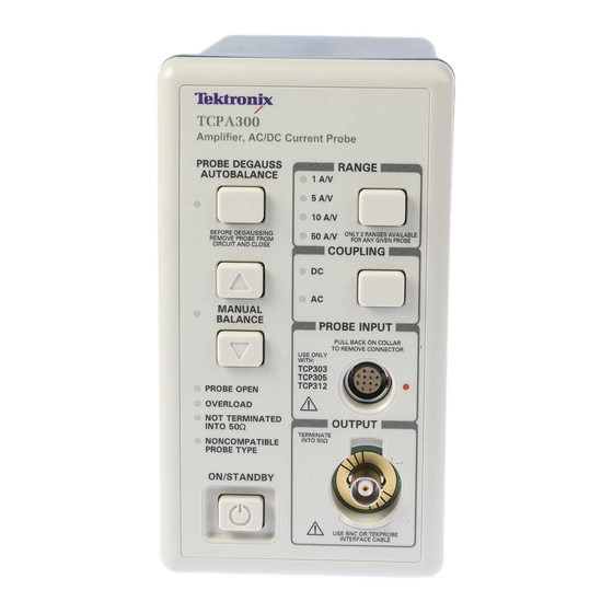
Tektronix TCPA300 User Manual
Series ac/dc current probes
Hide thumbs
Also See for TCPA300:
- Instruction manual (205 pages) ,
- Safety instructions (32 pages) ,
- User manual (80 pages)

Subscribe to Our Youtube Channel
Related Manuals for Tektronix TCPA300


Summary of Contents for Tektronix TCPA300
- Page 1 TCPA300/400 Amplifiers & TCP300A/400 Series AC/DC Current Probes User Manual *P077118301* 077-1183-01...
-
Page 3: User Manual
TCPA300/400 Amplifiers & TCP300A/400 Series AC/DC Current Probes User Manual This document applies for firmware version 1.0 and above. www.tektronix.com 077-1183-01... - Page 4 Copyright © Tektronix. All rights reserved. Licensed software products are owned by Tektronix or its subsidiaries or suppliers, and are protected by national copyright laws and international treaty provisions. Tektronix products are covered by U.S. and foreign patents, issued and pending. Information in this publication supersedes that in all previously published material.
- Page 5 Tektronix, with shipping charges prepaid. Tektronix shall pay for the return of the product to Customer if the shipment is to a location within the country in which the Tektronix service center is located. Customer shall be responsible for paying all shipping charges, duties, taxes, and any other charges for products returned to any other locations.
-
Page 7: Table Of Contents
Table of Contents General safety summary ................... Compliance Information ..................EMC Compliance (Applies to TCPA300 & TCPA400 Amplifiers Only) ......Safety Compliance Information ................viii Environmental Considerations ................Preface ......................Manual Conventions..................Getting Started ...................... System Configuration ..................Options......................Standard Accessories .................. - Page 8 Correcting the Cause of an Error Code..............Shutdown Error ....................Specifications ...................... Warranted Specifications..................Nominal and Typical Characteristics ............... Mechanical Characteristics .................. Environmental Characteristics ................Performance Graphs ..................TCP404XL Maximum Measurement Times............... Glossary Index TCPA300/400 Amplifiers and TCP300A/400 Series Current Probes User Manual...
- Page 9 Figure 34: Specified operating area of the probes ............. Figure 35: Measuring 750A noncontinuous at 50 °C ambient temperature......... Figure 36: Measuring 600A noncontinuous at 50 °C ambient temperature......... Figure 37: Measuring 750A noncontinuous at 23 °C ambient temperature......... TCPA300/400 Amplifiers and TCP300A/400 Series Current Probes User Manual...
- Page 10 Table 9: Nominal and typical amplifier characteristics............Table 10: TCPA300 and TCPA400 mechanical characteristics ..........Table 11: Probe mechanical characteristics..............Table 12: Shipping weights and dimensions ..............Table 13: Environmental characteristics ................ TCPA300/400 Amplifiers and TCP300A/400 Series Current Probes User Manual...
-
Page 11: General Safety Summary
Do not operate with suspected failures. If you suspect that there is damage to this product, have it inspected by qualified service personnel. Avoid exposed circuitry. Do not touch exposed connections and components when power is present. TCPA300/400 Amplifiers and TCP300A/400 Series Current Probes User Manual... - Page 12 WARNING indicates an injury hazard not immediately accessible as you read the marking. CAUTION indicates a hazard to property including the product. The following symbol(s) may appear on the product: TCPA300/400 Amplifiers and TCP300A/400 Series Current Probes User Manual...
-
Page 13: Compliance Information
Compliance Information This section lists the EMC (electromagnetic compliance) and environmental standards with which the instrument complies. EMC Compliance (Applies to TCPA300 & TCPA400 Amplifiers Only) EC Declaration of Meets intent of Directive 2004/108/EC for Electromagnetic Compatibility. Compliance was demonstrated to the following specifications as listed in the Conformity –... -
Page 14: Safety Compliance Information
CAT II. Local-level mains (wall sockets). Equipment at this level includes appliances, portable tools, and similar products. Equipment is usually cord-connected. CAT I. Secondary (signal level) or battery operated circuits of electronic equipment. viii TCPA300/400 Amplifiers and TCP300A/400 Series Current Probes User Manual... - Page 15 Pollution Degree 2 (as defined in IEC 61010-1). Note: Rated for indoor use only. The TCP305A and TCP312A Current Probes are exempt from the Low Voltage Directive and are not third-party listed. However, they have been evaluated to applicable safety standards. TCPA300/400 Amplifiers and TCP300A/400 Series Current Probes User Manual...
-
Page 16: Environmental Considerations
This product is classified as an industrial monitoring and control instrument accessory, and is not required to comply with the substance restrictions of the Substances recast RoHS Directive 2011/65/EU until July 22, 2017. TCPA300/400 Amplifiers and TCP300A/400 Series Current Probes User Manual... -
Page 17: Preface
Manual Conventions The term "amplifier" is used to refer to either the TCPA300 or TCPA400 when referring to common attributes. If a subject is unique to either amplifier, the amplifier will be referred to directly by model. - Page 18 Preface TCPA300/400 Amplifiers and TCP300A/400 Series Current Probes User Manual...
-
Page 19: Getting Started
Getting Started The TCPA300 and TCPA400 current probe amplifiers let you use one probe to simultaneously measure AC and DC current. The amplifiers convert the sensed current into a proportional voltage signal that you can measure directly with an oscilloscope. - Page 20 If the oscilloscope does not have an input that can be set to 50 Ω impedance, you need a feedthrough 50 Ω termination. This termination is included as a standard accessory with your TCPA300 and TCPA400 Current Probe Amplifiers. TCPA300/400 Amplifiers and TCP300A/400 Series Current Probes User Manual...
-
Page 21: Options
Getting Started Options Table 1-1 lists options that are available for the TCPA300 and TCPA400 amplifiers. Table 2: Amplifier options Option Description Universal Euro power cord United Kingdom power cord Australia power cord Switzerland power cord Japan power cord China power cord No power cord Tektronix service options that you can order for your amplifiers and probes are... -
Page 22: Standard Accessories
Getting Started Standard Accessories The following accessories are shipped with the amplifiers and probes. Amplifiers The following accessories are shipped with the TCPA300 and TCPA400 amplifiers. Power Cord (customer-chosen option) BNC Cable Termination, 50 Ω 2W TEKPROBE Interconnect Cable Documentation CD (Includes User Manual–English, Japanese, and Russian languages, and Service Manual–English only) -
Page 23: Probe Cover
You can attach the probe cover to the side of the bench to keep the probe off of your work surface. (See Figure 2.) Figure 2: Using the probe cover TCPA300/400 Amplifiers and TCP300A/400 Series Current Probes User Manual... -
Page 24: Ground Lead
RF currents which can flow into the probe cable. In some cases, it may be helpful to move the ground lead or reposition the probe away from noise sources in the circuit under test. TCPA300/400 Amplifiers and TCP300A/400 Series Current Probes User Manual... -
Page 25: Travel Case
Getting Started Travel Case The travel case is a recommended accessory for the TCPA300/400 Amplifiers. The travel case includes room to store one amplifier and two TCP300A/400 Series Current Probes, one of each size. (For example, you can store a TCP305A and a TCP303 probe.) A compartment is included to store associated cables and... -
Page 26: Connecting The Amplifier To An Oscilloscope
Getting Started Connecting the Amplifier to an Oscilloscope You will need an oscilloscope to display the TCPA300 and TCPA400 measurement output. To use the full dynamic range of the probe/amplifier combination, the oscilloscope must be capable of displaying a vertical scale factor of 1 mV/div to 1 V/div. -
Page 27: Connecting A Current Probe To The Amplifier
If a probe requires adjustment, information is available in the service manual. The adjustment procedure must be performed only by qualified service personnel. Contact your nearest Tektronix Service Center if you need more assistance. TCPA300/400 Amplifiers and TCP300A/400 Series Current Probes User Manual... -
Page 28: Operating The Current Probe Slide
(See Figure 6.) To open the probe, pull the slide back until the jaw is open. To lock the probe, push the slide forward until the detent snaps into place. Figure 6: TCP312A and TCP305A slide operation TCPA300/400 Amplifiers and TCP300A/400 Series Current Probes User Manual... -
Page 29: Figure 7: Unlock And Open The Tcp303 And Tcp404Xl
Figure 7: Unlock and open the TCP303 and TCP404XL 4. To lock the probe, release the squeeze handle. 5. Press the top of the lock button. Figure 8: Close and lock the TCP303 and TCP404XL TCPA300/400 Amplifiers and TCP300A/400 Series Current Probes User Manual... -
Page 30: Degaussing And Autobalancing The Current Probe
50 Ω input impedance. If this occurs, the NOT TERMINATED INTO 50 Ω LED lights on the amplifier front panel. After you have completed the oscilloscope adjustments and the amplifier degauss/autobalance procedure, your system is ready to measure current. TCPA300/400 Amplifiers and TCP300A/400 Series Current Probes User Manual... -
Page 31: Dc Measurements
(if necessary) using the amplifier MANUAL BALANCE controls. WARNING. The current probes can be used to measure current on uninsulated wires. However, the circuit must be de-energized when connecting or removing the current probe. TCPA300/400 Amplifiers and TCP300A/400 Series Current Probes User Manual... -
Page 32: Figure 9: Arrow On Current Probe Indicates Conventional Current Flow
flow will display the current waveform upside-down on the oscilloscope. 3. Adjust the oscilloscope time base, trigger, and gain as needed. Figure 9: Arrow on current probe indicates conventional current flow TCPA300/400 Amplifiers and TCP300A/400 Series Current Probes User Manual... -
Page 33: Ac Measurements
DC. Change only the amplifier coupling to AC. Using the oscilloscope AC coupling may cause the amplifier to exceed its output dynamic range. 6. Adjust the oscilloscope time base and trigger as needed. TCPA300/400 Amplifiers and TCP300A/400 Series Current Probes User Manual... - Page 34 Getting Started TCPA300/400 Amplifiers and TCP300A/400 Series Current Probes User Manual...
-
Page 35: Control Summary
Control Summary This section describes the function of each TCPA300 and TCPA400 front panel control and connector. The overview shows most functions and is followed by a detailed description. (See Figure 10.) Some seldom-used functions do not appear in the illustration. These functions are completely discussed in the detailed descriptions that follow this illustration. -
Page 36: Tcpa300 And Tcpa400 Controls
Control Summary 6. The current probes connect to the TCPA300 and TCPA400 at the PROBE INPUT connector. 7. The COUPLING button selects AC or DC probe coupling, as indicated by the LEDs. 8. The RANGE button toggles between the two scale factors that are available for the attached probe (TCPA300 only). - Page 37 When this LED is orange, it indicates that the safe operating temperature of the probe, and possibly the amplifier, has been exceeded. Disconnect the probe from the current source and allow time for the probe head and amplifier to cool. TCPA300/400 Amplifiers and TCP300A/400 Series Current Probes User Manual...
- Page 38 RANGE Button Press the RANGE button to toggle between the scale factors (sensitivity settings) of the probe attached to the TCPA300. If no RANGE LEDs are lit, this indicates a probe is not connected to the amplifier. COUPLING Button and The COUPLING button determines the coupling between the TCPA300/TCPA400 and the oscilloscope.
- Page 39 Degauss Autobalance Button.) PROBE INPUT Connector All current probes compatible with the TCPA300 and TCPA400 attach at the PROBE INPUT connector, which is a multi-pin female connector. Information about connecting a probe is available. (See page 9, Connecting a Current Probe to the Amplifier.)
- Page 40 GPIB Operation The TCPA300 and TCPA400 Current Probe Amplifiers do not have direct GPIB connections. However, you can use a computer to control the oscilloscope that the amplifier is connected to, enabling you to change the time and scale factors of your current measurements over the oscilloscope GPIB bus.
-
Page 41: Reference Notes
Reference Notes These notes are provided to help you utilize the full potential of the TCPA300 and TCPA400 current probe systems. Degaussing a Probe with an Unpowered Conductor in the Jaws Under almost all conditions, you can degauss your current probe while a conductor of an unpowered circuit is clamped in the jaws. -
Page 42: Measuring Differential Current
1. Orient the two conductors under test so that the polarities oppose each other. 2. Clamp the current probe around the two conductors as shown. Be careful not to pinch a conductor in the probe jaws. TCPA300/400 Amplifiers and TCP300A/400 Series Current Probes User Manual... -
Page 43: Figure 12: Measuring Differential Current And Nulls
Conventional current flows from positive to negative. 4. To adjust for a current null, adjust the current in one of the conductors until the displayed measurement is zero. TCPA300/400 Amplifiers and TCP300A/400 Series Current Probes User Manual... -
Page 44: Ac And Dc Coupling
Reference Notes AC and DC Coupling You can couple the signal input to the TCPA300 and TCPA400 with either DC or AC coupling. DC coupling shows the DC and AC measurement components while AC coupling removes the DC component from the displayed signal. When you use AC coupling, make sure that the input DC current does not exceed the probe specifications. -
Page 45: Maximum Current Limits
Exceeding these ratings can magnetize the probe and cause measurement errors. To determine if your measurement exceeds the Ampere-second product, perform either Procedure A (Maximum Allowable Pulse Width), or Procedure B (Maximum Allowable Pulse Amplitude). TCPA300/400 Amplifiers and TCP300A/400 Series Current Probes User Manual... -
Page 46: Figure 14: Applying The Amp-Second Product Rule
3. Check that the pulse width at the 50% point of the measured signal is less than the calculated maximum allowable pulse width (PW Figure 14: Applying the amp-second product rule TCPA300/400 Amplifiers and TCP300A/400 Series Current Probes User Manual... - Page 47 500 A-μs in the 10 A/V range setting. If a pulse measured with a TCP312A probe has a width of 15 μs, the maximum allowable peak current would be 500 A-μs divided by 15 μs, or 33.3 A. TCPA300/400 Amplifiers and TCP300A/400 Series Current Probes User Manual...
-
Page 48: Measuring Noncontinuous Current With The Tcp404Xl Probe
(See Figure 35 on page 58.) (See Figure 37 on page 59.) As the duty cycle increases on the x-axis, the measurement time (of the noncontinuous current) on the y-axis decreases. TCPA300/400 Amplifiers and TCP300A/400 Series Current Probes User Manual... - Page 49 750 A, and having a 20% duty cycle, a 27 °C increase in temperature yields a 12 minute decrease in maximum measurement time. Keep these factors into account when taking measurements to ensure accuracy and to protect both yourself from injury and the equipment from damage. TCPA300/400 Amplifiers and TCP300A/400 Series Current Probes User Manual...
-
Page 50: Extending Current Range
WARNING. To avoid personal injury or loss of life due to shock or fire, do not exceed the specified electrical limits of the TCPA300 and TCPA400 or any applicable accessories. When using multiple conductors, do not exceed current limits on either conductor. -
Page 51: Figure 16: Adding A Second Conductor
To determine measurement values, add the value of the bucking current to the displayed measurement. NOTE. Winding multiple turns to the probe increases the insertion impedance and reduces the upper bandwidth limit of the probe. TCPA300/400 Amplifiers and TCP300A/400 Series Current Probes User Manual... -
Page 52: Increasing Sensitivity
5 mA DC, the actual current flow is 5 mA divided by 5, or 1 mA DC. NOTE. Winding multiple turns around the probe increases insertion impedance and reduces the upper bandwidth limit of the probe. Figure 18: Increasing probe sensitivity TCPA300/400 Amplifiers and TCP300A/400 Series Current Probes User Manual... -
Page 53: Application Notes
Instrument Control Setting TCPA300 COUPLING RANGE 50 A/V Oscilloscope Coupling Amps/Division 10 A/Div (200 mV/Div) (Volts/Division if not using TEKPROBE interface cable) Zero-Current Reference Center graticule line Time Base 200 ms/division TCPA300/400 Amplifiers and TCP300A/400 Series Current Probes User Manual... -
Page 54: Figure 19: Setup For Measuring Charging Current
A single-phase diode failure normally appears as an extreme drop in charge current every third cycle, waveform (b). (See Figure 20.) Figure 20: Charge current waveforms TCPA300/400 Amplifiers and TCP300A/400 Series Current Probes User Manual... -
Page 55: Inductance Measurements
Application Notes Inductance Measurements You can use the TCPA300 and TCPA400 to measure inductance of coils. Two different methods can be used: one for low-impedance pulse sources and another for high-impedance pulse sources of known value. Low-Impedance Pulse This figure shows a constant-voltage pulse generator of extremely low output impedance connected to an inductor that has low resistance. -
Page 56: Figure 22: Linear Current Vs. Time Ramp
5. Calculate the inductance using the following formula: where: L is the inductance in henries, E is the voltage of the pulse generator, dt is the change in time, and di is the change in current. TCPA300/400 Amplifiers and TCP300A/400 Series Current Probes User Manual... -
Page 57: Continuity Test Of Multiple-Conductor Cable
Figure 23: High-impedance source current ramp Continuity Test of Multiple-Conductor Cable Single conductors in a multiconductor cable can be tested with the TCPA300 and TCPA400. To check a conductor, clamp the current probe around the cable bundle and check for a specific, known current signal. If there is no current or the current is abnormally low, then the conductor has a continuity problem. -
Page 58: Measuring Inductor Turns Count
2. Insert the reference coil into the current probe. 3. Insert the test coil into the current probe so that the currents oppose each other as shown. (See Figure 25.) Figure 25: Turns measurement using reference coil TCPA300/400 Amplifiers and TCP300A/400 Series Current Probes User Manual... -
Page 59: Power Measurement And Analysis Software
Modulation analysis After making the measurements, the software generates detailed test reports in customizable formats. When the software is used with a Tektronix TDS5000 Series or TDS7054/TDS7104 digital phosphor oscilloscope and differential voltage and current probes, it forms a complete measurement system for power supply design and test. -
Page 60: Troubleshooting And Error Codes
Troubleshooting and Error Codes Troubleshooting and Error Codes Possible problems that you may encounter when measuring current with the TCPA300 and TCPA400 are available. (See Table 6.) Use this as a quick troubleshooting reference. Table 6: Troubleshooting Problem Remedy Amplifier will not power on Check that the amplifier is plugged into a working AC outlet. - Page 61 Amplifier output is not terminated into 50 Ω load. Set input impedance of oscilloscope to 50 Ω or connect a 50 Ω feedthrough termination at the oscilloscope input, not at the amplifier output. Defective current probe transformer. TCPA300/400 Amplifiers and TCP300A/400 Series Current Probes User Manual...
- Page 62 The measurement exceeds the Ampere-second product of the Current Probe. The oscilloscope bandwidth limit is turned on. Verify that the bandwidth limit switch on the oscilloscope is set to the desired bandwidth position. TCPA300/400 Amplifiers and TCP300A/400 Series Current Probes User Manual...
-
Page 63: Displaying Error Codes With The Probe Degauss Autobalance Button
4. To continue past an error code, press any button except ON/STANDBY. However, the degauss will fail until the internal error condition is corrected and the degauss operation is run again. Figure 26: Error code display TCPA300/400 Amplifiers and TCP300A/400 Series Current Probes User Manual... -
Page 64: Figure 27: Interpreting The Error Code Display
Degauss/Autobalance adjustment routine again. If the adjusting the Overload error reoccurs, then remove the probe from the circuit. trip points. If this does not resolve the error, the amplifier needs service. Unused TCPA300/400 Amplifiers and TCP300A/400 Series Current Probes User Manual... -
Page 65: Correcting The Cause Of An Error Code
If the measurement you were taking was within the probe and amplifier specifications, degauss the probe and take the measurement again. If the shutdown error persists, contact your Tektronix Service Center. TCPA300/400 Amplifiers and TCP300A/400 Series Current Probes User Manual... - Page 66 Troubleshooting and Error Codes TCPA300/400 Amplifiers and TCP300A/400 Series Current Probes User Manual...
-
Page 67: Specifications
≤3% ≤3% ≤3% Typical ≤1% ≤1% ≤1% ≤1% Warranted from 10 °C to 50 °C. For temperature range of 0 °C to <10 °C, spec is +3%/-6%. 23 °C ±5 °C TCPA300/400 Amplifiers and TCP300A/400 Series Current Probes User Manual... -
Page 68: Nominal And Typical Characteristics
21 A 35 A 150 A 500 A RMS (sinusoidal) Peak Pulse 50 A 50 A 500 A 750 A Low Current Range 1 A/V Range 5 A/V Range 5 A/V Range TCPA300/400 Amplifiers and TCP300A/400 Series Current Probes User Manual... -
Page 69: Mechanical Characteristics
Mechanical Characteristics Table 10: TCPA300 and TCPA400 mechanical characteristics Parameter, nominal Characteristic Length 173 mm (6.8 in) Width 91.4 mm (3.6 in) Height 167 mm (6.6 in) Weight 1.14 kg (2.5 lb) TCPA300/400 Amplifiers and TCP300A/400 Series Current Probes User Manual... -
Page 70: Figure 28: Probe Jaw Dimensions (Nominal)
254 mm (10.00 inches) 108 mm (4.25 inches) 127 mm (5.00 inches) 127 mm (5.00 inches) Weight 2.7 kg (6.00 lb) 0.585 kg (1.29 lb) 1.33 kg (2.93 lb) 1.55 kg (3.42 lb) TCPA300/400 Amplifiers and TCP300A/400 Series Current Probes User Manual... -
Page 71: Environmental Characteristics
3.48 g , 5 Hz to 500 Hz, 10 minutes each axis Shock, Amplifiers 50 g, 11 ms duration, half-sine pulses Electro-Magnetic Compliance Meets FCC Part 15, Subpart B, Class A TCPA300/400 Amplifiers and TCP300A/400 Series Current Probes User Manual... -
Page 72: Performance Graphs
Specifications Performance Graphs Figure 29: Frequency derating-TCP312A Figure 30: Frequency derating-TCP305A Figure 31: Frequency derating-TCP303 TCPA300/400 Amplifiers and TCP300A/400 Series Current Probes User Manual... -
Page 73: Figure 32: Frequency Derating-Tcp404Xl
Specifications Figure 32: Frequency derating-TCP404XL TCPA300/400 Amplifiers and TCP300A/400 Series Current Probes User Manual... -
Page 74: Figure 33: Insertion Impedance Versus Frequency
Specifications Figure 33: Insertion impedance versus frequency TCPA300/400 Amplifiers and TCP300A/400 Series Current Probes User Manual... -
Page 75: Figure 34: Specified Operating Area Of The Probes
Specifications Figure 34: Specified operating area of the probes TCPA300/400 Amplifiers and TCP300A/400 Series Current Probes User Manual... -
Page 76: Tcp404Xl Maximum Measurement Times
(See page 30, Measuring Noncontinuous Current with the TCP404XL Probe.) Figure 35: Measuring 750A noncontinuous at 50 °C ambient temperature Figure 36: Measuring 600A noncontinuous at 50 °C ambient temperature TCPA300/400 Amplifiers and TCP300A/400 Series Current Probes User Manual... -
Page 77: Figure 37: Measuring 750A Noncontinuous At 23 °C Ambient Temperature
At 23 degrees ambient temperature, 600 A can be measured continuously with the TCP404XL probe. Emissions which exceed the levels required by this standard may occur when this equipment is connected to a test object. TCPA300/400 Amplifiers and TCP300A/400 Series Current Probes User Manual... - Page 78 Specifications TCPA300/400 Amplifiers and TCP300A/400 Series Current Probes User Manual...
- Page 79 Current fed back by the TCPA300 and TCPA400 to the current probe during DC and low-frequency AC measurements. Bucking current nulls most of the magnetic field in the probe core, allowing linear DC and AC measurements simultaneously.
- Page 80 After saturation occurs, the probe core usually retains residual magnetism, which continues to produce inaccuracies until the probe is degaussed. The probe should be degaussed after saturation occurs. TCPA300/400 Amplifiers and TCP300A/400 Series Current Probes User Manual...
- Page 81 20 Increasing probe sensitivity, 34 indicator, 20 Coupling modes, 26 NOT TERMINATED INTO 50 Current limitations OHMS indicator, 20 amp-second product, 27 Null current, 24 maximum continuous, 27 maximum pulsed, 27 TCPA300/400 Amplifiers and TCP300A/400 Series Current Probes User Manual...
- Page 82 18 TEKPROBE-to-TEKPROBE saturation, 27 PROBE interface cable, 8 DEGAUSS/AUTOBALANCE Termination, 50 Ω feedthrough, 8 indicator, 18 Travel case, 7 RANGE button and indicator, 20 PROBE INPUT connector, 21 Troubleshooting, 42 TCPA300/400 Amplifiers and TCP300A/400 Series Current Probes User Manual...
Need help?
Do you have a question about the TCPA300 and is the answer not in the manual?
Questions and answers