MacDon D1X Series Operator's Manual
Draper header for self-propelled windrowers
Hide thumbs
Also See for D1X Series:
- Operator's manual (308 pages) ,
- Unloading and assembly instructions (124 pages) ,
- Assembly instructions manual (108 pages)
Table of Contents

Subscribe to Our Youtube Channel
Related Manuals for MacDon D1X Series


Summary of Contents for MacDon D1X Series
- Page 1 D1X Series Draper Header for Self-Propelled Windrowers IMPORTANT: PAGE 29 HAS BEEN UPDATED SINCE THIS MANUAL WAS PUBLISHED. Operator’s Manual 214044 Revision A Model Year 2017 Original Instruction The harvesting specialists.
- Page 2 D1X Series Draper Header for Self-Propelled Windrowers Published: November 2016...
- Page 3 This instructional manual contains information on the D1X Series Draper Header. Teamed with your windrower, the D1X Series Draper Header will cut and lay crop into fluffy, uniform windrows. The D1X Series Draper Header is designed as a straight-cut header, equipped to work well in all straight-cut conditions whether cutting on or above the ground.
- Page 4 Windrower, page 94 hose management arm latch support to/from storage/transport position. Revised image; beater bars not applicable to Every 250 Hours, page 109 D1X Series. Added note. Adjusting Reel Clearance, page 176 Updated bundle numbers. • 6.2.2 Vertical Knife Mounts, page 217 •...
- Page 5 Summary of Change Refer to Removed topics that are not applicable to D1X Series draper headers. • Battery Safety • PR15 Tine Tube Reel Conversion Kit • Cutterbar Wearplate • Knifehead Shield • Hydraulic Deck Shift Package • Upper Cross Auger Hydraulic Kit for Double Draper Drive •...
- Page 6 Model and Serial Number Record the model number, serial number, and model year of the header and Slow Speed Transport/Stabilizer Wheel option (if installed) on the lines below. NOTE: Right-hand (RH) and left-hand (LH) designations are determined from the operator’s position, facing forward. Header Model: Serial Number: Year:...
-
Page 7: Table Of Contents
TABLE OF CONTENTS Introduction ............................i List of Revisions ..........................ii Model and Serial Number.........................iv Safety ..............................1 Safety Alert Symbols........................1 Signal Words........................... 2 General Safety ..........................3 Maintenance Safety ......................... 5 Hydraulic Safety ..........................6 Safety Signs ............................ 7 1.6.1 Installing Safety Decals ...................... - Page 8 TABLE OF CONTENTS 3.7.10 Reel Tine Pitch........................55 Reel Cam Settings ......................55 Adjusting Reel Cam ......................57 3.7.11 Crop Dividers ......................... 57 Removing Crop Dividers with Latch Option from Header ........... 57 Removing Crop Dividers without Latch Option from Header..........58 Installing Crop Dividers with Latch Option onto Header .............
- Page 9 TABLE OF CONTENTS 5.3.2 Break-In Inspection .......................102 5.3.3 Preseason Servicing......................102 5.3.4 End-of-Season Service ......................103 5.3.5 Checking Hydraulic Hoses and Lines..................104 5.3.6 Lubrication and Servicing.......................104 Greasing Procedure.......................105 Service Intervals ......................106 Electrical System .......................... 112 5.4.1 Replacing Light Bulbs ......................113 5.4.2 Checking and Adjusting Reel Height Sensor ................
- Page 10 TABLE OF CONTENTS 5.8.2 Reel Frown ...........................177 Adjusting Reel Frown .....................177 5.8.3 Centering the Reel ........................178 Centering Double Reels ....................179 Centering Single Reels....................179 5.8.4 Reel Fingers .........................179 Removing Steel Fingers ....................180 Installing Steel Fingers ....................180 Removing Plastic Fingers ....................181 Installing Plastic Fingers....................181 5.8.5 Tine Tube Bushings.......................182 Removing Bushings from Five-, Six-, or Nine-Bat Reels ...........182...
- Page 11 TABLE OF CONTENTS 6.4.1 Double Draper Drive (DDD) Kit....................220 6.4.2 Draper Deflector (Narrow)......................220 6.4.3 Draper Deflector (Wide) ......................220 6.4.4 Draper Extension Kit......................221 6.4.5 Swath Rods ..........................221 6.4.6 Upper Cross Auger (UCA) .....................221 6.4.7 Rice Divider Rods .........................222 Unloading and Assembly ........................223 Troubleshooting ..........................225 Crop Loss at Cutterbar ........................225 Cutting Action and Knife Components ....................227...
-
Page 13: Safety
1 Safety 1.1 Safety Alert Symbols This safety alert symbol indicates important safety messages in this manual and on safety signs on the machine. This symbol means: • ATTENTION! • BECOME ALERT! • YOUR SAFETY IS INVOLVED! Carefully read follow safety message accompanying this symbol. -
Page 14: Signal Words
SAFETY 1.2 Signal Words Three signal words, DANGER, WARNING, and CAUTION, are used to alert you to hazardous situations. The appropriate signal word for each situation has been selected using the following guidelines: DANGER Indicates an imminently hazardous situation that, if not avoided, will result in death or serious injury. WARNING Indicates a potentially hazardous situation that, if not avoided, could result in death or serious injury. -
Page 15: General Safety
SAFETY 1.3 General Safety CAUTION The following are general farm safety precautions that should be part of your operating procedure for all types of machinery. Protect yourself. • When assembling, operating, and servicing machinery, wear all protective clothing and personal safety devices that could be necessary for job at hand. - Page 16 SAFETY • Wear close-fitting clothing and cover long hair. Never wear dangling items such as scarves or bracelets. • Keep all shields in place. NEVER alter or remove safety equipment. Make sure driveline guards can rotate independently of shaft and can telescope freely. •...
-
Page 17: Maintenance Safety
SAFETY 1.4 Maintenance Safety To ensure your safety while maintaining machine: • Review operator’s manual and all safety items before operation and/or maintenance of machine. • Place all controls in Neutral, stop the engine, set the park brake, remove the ignition key, and wait for all moving parts to stop before servicing, adjusting, and/or repairing. -
Page 18: Hydraulic Safety
SAFETY 1.5 Hydraulic Safety • Always place hydraulic controls Neutral before dismounting. • Make sure that all components in hydraulic system are kept clean and in good condition. • Replace any worn, cut, abraded, flattened, or crimped hoses and steel lines. •... -
Page 19: Safety Signs
SAFETY 1.6 Safety Signs • Keep safety signs clean and legible at all times. • Replace safety signs that missing become illegible. • If original parts on which a safety sign was installed are replaced, be sure repair part also bears current safety sign. -
Page 20: Safety Decal Locations
SAFETY 1.7 Safety Decal Locations Figure 1.15: Upper Cross Auger A - MD #279085 Figure 1.16: Slow Speed Transport A - MD #220799 214044 Revision A... - Page 21 SAFETY Figure 1.17: Slow Speed Transport Tow-Bar A - MD #220797 B - MD #220798 Figure 1.18: Vertical Knife A - MD #174684 214044 Revision A...
- Page 22 SAFETY Figure 1.19: Endsheets, Reel Arms, and Backsheet A - MD #184422 (Four Places) B - MD #131393 C - MD #174632 D - MD #166466 (Two Places) E - MD #131392 Double Reel – MD #131393 F - MD #131391 (Two Places) Single Reel (Two Places) 214044 Revision A...
- Page 23 SAFETY Figure 1.20: 35-Foot Header Backtube (30-Foot Header Similar) A - MD #184372 B - MD #166466 C - MD #131391 D - MD #131392 (35-Ft Double Reel Only) 214044 Revision A...
- Page 24 SAFETY Figure 1.21: 40-Foot Header Backtube (45-Foot Header Similar) A - MD #184372 B - MD #131392 C - MD #166466 D - MD #131391 214044 Revision A...
-
Page 25: Understanding Safety Signs
SAFETY 1.8 Understanding Safety Signs MD #113482 General hazard pertaining machine operation and servicing CAUTION To avoid injury or death from improper or unsafe machine operation: • Read the operator’s manual and follow all safety instructions. If you do not have a manual, obtain one from your Dealer. - Page 26 SAFETY MD #131392 Crushing hazard WARNING • To avoid injury from fall of raised reel; fully raise reel, stop the engine, remove the key, and engage safety prop on each reel support arm before working on or under reel. Figure 1.24: MD #131392 MD #131393 Reel hazard WARNING...
- Page 27 SAFETY MD #174436 High pressure oil hazard WARNING • Do not go near leaks. • High pressure oil easily punctures skin causing serious injury, gangrene, or death. • If injured, seek emergency medical help. Immediate surgery is required to remove oil. •...
- Page 28 SAFETY MD #184372 General hazard pertaining machine operation and servicing CAUTION To avoid injury or death from improper or unsafe machine operation: • Read the operator’s manual and follow all safety instructions. If you do not have a manual, obtain one from your Dealer.
- Page 29 SAFETY MD #193147 Transport/roading hazard WARNING • Ensure tow-bar lock mechanism is locked. Figure 1.32: MD #193147 MD #220797 Tipping hazard in transport mode WARNING • Read the operator’s manual for more information on potential tipping or roll-over of header while transporting. Figure 1.33: MD #220797 MD #220798 Loss of control hazard in transport...
- Page 30 SAFETY MD #220799 Transport/roading hazard WARNING • Ensure tow-bar lock mechanism is locked. Figure 1.35: MD #220799 MD #279085 Auger entanglement hazard WARNING • To avoid injury from rotating auger, stand clear of auger while machine is running. Figure 1.36: MD #279085 214044 Revision A...
-
Page 31: Product Overview
CGVW Combined vehicle gross weight D1X Series header MacDon D125X rigid draper headers for windrowers MacDon D130XL, D135XL, D140XL, and D145XL rigid draper headers for D1XL Series header windrowers. Double knife Double-knife drive Double-draper drive... - Page 32 PRODUCT OVERVIEW Term Definition Knife A cutting device which uses a reciprocating cutter (also called a sickle) Not applicable An internally threaded fastener that is designed to be paired with a bolt N-DETENT The slot opposite the NEUTRAL position on operator’s console North American header Header configuration typical in North America National Pipe Thread: A style of fitting used for low pressure port openings Threads...
- Page 33 PRODUCT OVERVIEW Term Definition A thin cylinder with a hole or slot located in the center that is to be used as a spacer, Washer load distribution element, or a locking mechanism Windrower Power unit of a self-propelled header Windrower control module 214044 Revision A...
-
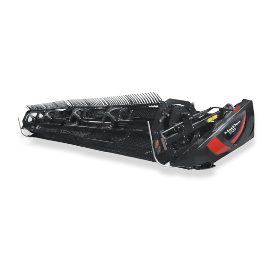
Page 34: Component Identification
PRODUCT OVERVIEW 2.2 Component Identification Figure 2.1: Windrower Header Components A - Reel Cam B - Pick-Up Reel Tines C - Draper D - Center Reel Arm Prop Handle E - Hydraulic Connections F - Transport Light G - Reel Safety Prop H - Endshield J - Reel Lift Cylinder K - Skid Shoe... -
Page 35: Specifications
PRODUCT OVERVIEW 2.3 Specifications The following symbol and letters are used in Table and Table 2.1 Header Specifications, page 23 2.2 Header Attachments, page • S: standard • O : optional (factory installed) • O : optional (dealer installed) • — : not available Table 2.1 Header Specifications Cutterbar Effective cutting width (distance between crop divider points) - Page 36 PRODUCT OVERVIEW Knife Sections Over-serrated / solid / bolted / 9 serrations per inch Over-serrated / solid / bolted / 14 serrations per inch Knife overlap at center (double-knife headers) 3 mm (1/8 in.) Guards and Hold-Downs Guard: pointed / forged / double heat treated (DHT) Hold-down: sheet metal / adjustment bolt Guard: stub / forged bottom / forged top / adjustment plate Guard: stub / forged bottom / sheet metal top / adjustment bolt...
- Page 37 PRODUCT OVERVIEW Frame and Structure Cut width + 384 mm Header width (field mode) (15-1/8 in.) (long dividers D1XL 2845 mm (112 in.) installed) Series Header width (transport headers (long dividers mode—reel fore-aft fully 2667 mm (105 in.) only removed) retracted) D125X (long dividers...
- Page 38 PRODUCT OVERVIEW Table 2.2 Header Attachments Attachments Upper Cross Auger Outside diameter 305 mm (12 in.) Tube diameter All sizes 152 mm (6 in.) Stabilizer Wheel / Slow Speed Transport Wheels 15 in. Tires P205/75 R-15 Weight Estimated weight range with base header (variances are due to different package configurations) 25-foot header (D125X) 1753 kg (3872 lb.) 30-foot header (D130XL)
-
Page 39: Operation
• It is your responsibility to read and understand this manual completely before operating the header. Contact your MacDon Dealer if an instruction is not clear to you. • Follow all safety messages in the manual and on safety decals on the machine. -
Page 40: Operational Safety
OPERATION 3.2 Operational Safety CAUTION Adhere to the following safety precautions: • Follow all safety and operational instructions provided in your operator’s manuals. If you do not have a windrower manual, get one from your Dealer and read it thoroughly. •... -
Page 41: Header Safety Props
OPERATION 3.2.1 Header Safety Props The header safety props, located on the header lift cylinders, prevent the lift cylinders from unexpectedly retracting and lowering the header. Refer to your windrower operator’s manual for instructions. DANGER To avoid bodily injury or death from unexpected start-up or fall of raised machine, always stop engine, remove key, and engage safety props before going under header for any reason. -
Page 42: Disengaging Reel Safety Props
OPERATION 3. Use handle (A) to move lock rod to inboard position (B), which engages pin (C) under prop. 4. Lower reel until safety props contact the outer arm cylinder mounts and the center arm pins. Figure 3.4: Reel Safety Prop – Center Arm Disengaging Reel Safety Props 1. -
Page 43: Endshields
OPERATION 3. Use the handle (B) to move the lock rod (A) to the outboard position. Figure 3.6: Reel Safety Prop – Center Arm 3.2.3 Endshields A hinged, polyethylene endshield is fitted on each end of the header. Opening Endshields 1. -
Page 44: Closing Endshields
OPERATION 4. Pull the endshield free of hinge tab (A) if additional clearance is required, and swing shield towards the rear of the header. 5. Engage safety latch (B) on hinge arm to secure the shield in fully open position. Figure 3.9: Left Endshield Closing Endshields 1. -
Page 45: Removing Endshields
OPERATION Removing Endshields 1. Fully open endshield. Refer to Opening Endshields, page 2. Engage lock (A) to prevent endshield movement. 3. Remove self-tapping screw (B). 4. Slide endshield upwards and remove from hinge arm. 5. Place endshield away from work area. Figure 3.12: Left Endshield Installing Endshields 1. -
Page 46: Checking And Adjusting Endshields
OPERATION Checking and Adjusting Endshields Endshields are subject to expansion or contraction caused by large temperature variations. The position of the top pin and lower latch can be adjusted to compensate for dimensional changes. 1. Check gap (X) between front end of shields and header frame and compare to the values in Table 3.1 Endshield Gap at Various Temperatures, page... -
Page 47: Daily Start-Up Check
OPERATION 3. Loosen the three bolts (A) on latch assembly (B). 4. Adjust latch assembly (B) to achieve the desired gap between the front end of shield and header frame in accordance with Table 3.1 Endshield Gap at Various Temperatures, page 5. -
Page 48: Break-In Period
OPERATION 3.3 Break-in Period CAUTION Before investigating an unusual sound or attempting to correct a problem, shut off engine and remove key. NOTE: Until you become familiar with the sound and feel of your new header, be extra alert and attentive. After attaching the header to the windrower for the first time, follow these steps: 1. -
Page 49: Shutting Down The Machine
OPERATION 3.4 Shutting down the Machine DANGER To avoid bodily injury or death from unexpected start-up of machine, always stop engine and remove key from ignition before leaving operator’s seat for any reason. To shut down, and before leaving the windrower seat for any reason, follow these steps: 1. -
Page 50: Cab Controls
OPERATION 3.5 Cab Controls CAUTION Be sure all bystanders are clear of machine before starting engine or engaging any header drives. Refer to your windrower operator’s manual for identification of the following in-cab controls: • Header engage/disengage control • Header height •... -
Page 51: Header Setup
3.6 Header Setup 3.6.1 Header Attachments Several attachments to improve the performance of your header are available as options that can be installed by your MacDon Dealer. Refer to for descriptions of available items. 6 Options and Attachments, page 215 3.6.2 Header Settings... - Page 52 OPERATION 214044 Revision A...
- Page 53 OPERATION 214044 Revision A...
-
Page 54: Reel Settings
OPERATION 3.6.3 Reel Settings Table illustrates the profile of the reel at each cam or finger pitch setting 3.3 Recommended Reel Settings, page 42 as well as the reel position relative to the ground at different positions on the reel arm. Refer to 3.6.2 Header Settings, for the applicability of each finger pattern and reel position. - Page 55 OPERATION Cam Setting Number Reel Position Reel Finger Pattern (Finger Speed Gain) Number 3 (30%) 6 or 7 4 (35%) 2 or 3 NOTE: • Adjust the reel forward to get closer to the ground while tilting the header back. Fingers/tines will dig into the ground at extreme reel-forward positions, so adjust skid shoes or header angle to compensate.
-
Page 56: Header Operating Variables
OPERATION 3.7 Header Operating Variables Satisfactory function of the header in all situations requires making proper adjustments to suit various crops and conditions. Correct operation reduces crop loss and increases productivity. As well, proper adjustments and timely maintenance will increase the length of service you receive from your machine. The variables listed in Table and detailed on the following pages will affect the 3.4 Operating Variables, page 44... - Page 57 OPERATION Adjusting Stabilizer / Slow Speed Transport Wheels A properly adjusted header will achieve a balance between the amount of header weight carried by the float and the amount carried by the stabilizer / slow speed transport wheels. Refer to for recommended use in specific crops and crop conditions.
- Page 58 OPERATION 13. Lower header to desired cutting height using the windrower controls. 14. Check the load indicator. Figure 3.20: Load Indicator IMPORTANT: Continuous operation with excessive spring compression (i.e., load indicator reading greater than ‘4’ or a compressed length (A) less than 295 mm [11-5/8 in.]) can result in damage to the suspension system.
- Page 59 OPERATION 3. Support the wheel weight by lifting slightly with one hand on handle (B), and pull up on handle (A) to release lock. 4. Lift the wheel using handle (B), and engage the support channel into center slot (C) in upper support. 5.
-
Page 60: Cutting On The Ground
OPERATION Cutting on the Ground Cutting on the ground is performed with the header fully lowered and the cutterbar on the ground. The orientation of the knife and knife guards relative to the ground (header angle) is controlled by the skid shoes and the center-link—it is NOT controlled by the header lift cylinders. -
Page 61: Header Float
OPERATION IMPORTANT: Note the adjustment hole position on support (A) and ensure each skid shoe is set to the same position. 3. Remove lynch pin (B) from each skid shoe. 4. Hold shoe and remove pin (C) by disengaging from frame and pulling away from shoe. -
Page 62: Header Angle
OPERATION 3.7.3 Header Angle Header angle is adjustable to accommodate different crop conditions and/or soil types. Header angle (A) controls the distance (B) between the knife and the ground and is a critical component for effective cutting on the ground. Adjusting the center-link determines the position of the knife and guards and pivots the header at the point of skid shoe/ground contact (C). -
Page 63: Optional Reel Drive Sprockets
Other sprockets are available that provide more torque to the reel in heavy cutting conditions or allow for higher reel speeds in light crops when operating at increased ground speeds. See your MacDon Dealer for ordering information. For installation details, refer to 5.9.3 Reel Drive Sprocket, page... -
Page 64: Draper Speed
OPERATION Figure 3.28: Ground Speed vs Acres A - 15 Foot B - 20 Foot C - 25 Foot D - 30 Foot E - 35 Foot F - 40 Foot J - hectares per hour G - acres/hour H - miles/hour K - kilometers/hour Example: A 25-foot header operating at a ground speed of 9.7 km/h (6 mph) would produce a cut area of approximately 7.3 hectares (18 acres) in one hour. -
Page 65: Knife Speed
OPERATION 3.7.7 Knife Speed The header knife drive is powered by the windrower Table 3.5 D1X Series SP Knife Speed hydraulic pump and is controlled using the windrower Header Size Recommended Knife Speed Harvest Performance Tracker (HPT) (refer to your (ft.) -
Page 66: Reel Fore-Aft Position
OPERATION 3.7.9 Reel Fore-Aft Position Reel fore-aft position is a critical factor for achieving the best results in adverse conditions. The reel position is factory-set for normal conditions, but it can be adjusted forwards or backwards as required using the controls inside the cab. -
Page 67: Reel Tine Pitch
OPERATION 3.7.10 Reel Tine Pitch IMPORTANT: The following describes the conceptual and operational guidelines of the pick-up reel. Please read carefully before operating the machine. The pick-up reel is designed to pick up flattened and severely lodged crops. Because the cam setting is mainly used to determine how the crop gets delivered onto the drapers, it is not always necessary to increase the tine pitch (select a higher cam setting) to pick up lodged crops. - Page 68 OPERATION Cam Position 3, Reel Position 6 or 7 is mainly used to leave long stubble. • This position allows the reel to reach forward and lift the crop across the knife and onto the drapers. • This setting generates a fingertip speed that is approximately 30% faster than the reel speed.
-
Page 69: Adjusting Reel Cam
OPERATION IMPORTANT: The reel to cutterbar clearance should always be checked following adjustments to reel tine pitch and reel fore-aft position (refer to 175). Refer to 5.8.1 Reel Clearance to Cutterbar, page 3.6.2 Header Settings, page 39 for recommended reel tine pitch in specific crops and crop conditions. Adjusting Reel Cam DANGER To avoid bodily injury or death from unexpected start-up of machine, always stop engine and remove key... -
Page 70: Removing Crop Dividers Without Latch Option From Header
OPERATION 3. Lift safety lever (A). 4. Hold onto crop divider (B), push lever (C) to open latch, and lower crop divider. Figure 3.36: Crop Divider 5. Lift crop divider off endsheet and store as follows: a. Insert pin (A) on crop divider into hole in endsheet at location shown. -
Page 71: Installing Crop Dividers With Latch Option Onto Header
OPERATION 5. Remove bolt (A), lock washer, and flat washer. 6. Lower crop divider (B) and then lift to remove from endsheet. 7. Close or install endshields. Refer to 3.2.3 Endshields, page Figure 3.38: Crop Divider Installing Crop Dividers with Latch Option onto Header DANGER To avoid bodily injury or death from unexpected start-up or fall of raised machine, always stop engine, remove key, and engage safety props before going under header for any reason. -
Page 72: Installing Crop Dividers Without Latch Option Onto Header
OPERATION 6. Position crop divider as shown by inserting lugs (A) into holes in endsheet. 7. Lift forward end of crop divider until pin (B) at top of crop divider engages and closes latch (C). 8. Push safety lever (D) downwards to lock pin into latch (C). - Page 73 OPERATION 5. Remove crop divider from storage location by lifting crop divider to disengage lugs (A) at lower end and then lowering it slightly to disengage pin (B) from endsheet. Figure 3.42: Stored Crop Divider 6. Position crop divider as shown by inserting lugs (A) into holes in endsheet.
-
Page 74: Crop Divider Rods
OPERATION 3.7.12 Crop Divider Rods Crop divider rods are used in conjunction with crop dividers. The removable crop divider rods are most useful when crop is down. In standing crops, using only crop dividers is recommended. Table 3.6 Crop Divider Rods Recommended Use With Divider Rods Without Divider Rods Alfalfa... -
Page 75: Installing Crop Divider Rods
OPERATION Installing Crop Divider Rods 1. Remove crop divider rods from storage location on inboard of right side endsheet. Figure 3.47: Right Side Endsheet 2. Position crop divider rod (B) on tip of crop divider as shown and tighten bolt (A). 3. -
Page 76: Delivery Opening
OPERATION 3.8 Delivery Opening The width and location of the delivery opening affects the width and configuration of the windrow. The decision to widen or narrow the center delivery opening, or to double windrow, should be based on the following factors: •... -
Page 77: Adjusting Delivery Opening On Header Using Hydraulic Deck Shift
OPERATION 3.8.2 Adjusting Delivery Opening on Header using Hydraulic Deck Shift The delivery opening can be adjusted by moving the inboard deck shift stops. Adjusting inboard deck shift stop 1. Remove two 1/4 in. hex head bolts (A) and nuts. 2. -
Page 78: Double Windrowing
OPERATION 3.9 Double Windrowing Double windrowing involves laying two swaths side-by-side. Larger capacity combines or forage harvesters can then pick up twice as much material in a single pass which saves time and fuel. Double windrowing is performed using the header’s deck shifting ability. Deck shifting is used for crops that don’t require conditioning such as grains, canola, and beans. -
Page 79: Windrow Types
OPERATION 3.10 Windrow Types The following criteria determine windrow quality: • Weight Distribution: Heads and stalks distributed evenly across full width of windrow. • Good Curing: A loose, open windrow for better drying. • Good Weatherability: A well-formed windrow that supports heads off the ground and holds together in extreme weather conditions. - Page 80 OPERATION Machine Weight Windrow Type Description Curing Weatherability Setting Distribution Guidelines The stalks are lined • Low reel 45° diagonal along one edge speed and heads are lined along opposite • Less edge, 45° to windrow aggressive perpendicular. This tine pitch Poor Fair Poor...
-
Page 81: Haying Tips
OPERATION 3.11 Haying Tips 3.11.1 Curing Curing crops quickly helps maintain the highest quality because for each day that hay lies on the ground, 5% of the protein is lost. Leaving the windrow as wide and fluffy as possible results in the quickest curing. Cured hay should be baled as soon as possible. -
Page 82: Driving On Windrow
OPERATION Table 3.9 Recommended Windrow Characteristics Advantage Characteristic Enables airflow through windrow which is more important to the curing High and fluffy process than direct sunlight Consistent formation (not bunching) Permits an even flow of material into the baler, chopper, etc. Even distribution of material Results in even and consistent bales to minimize handling and across windrow... -
Page 83: Levelling The Header
OPERATION 3.12 Levelling the Header The windrower linkages are factory-set to provide the proper level for the header and should not normally require adjustment. NOTE: The float springs are NOT used to level the header. If the header is not level, check the pressure of the windrower’s tires to ensure proper inflation (refer to your windrower operator’s manual). -
Page 84: Unplugging The Cutterbar
OPERATION 3.13 Unplugging the Cutterbar DANGER To avoid bodily injury or death from unexpected start-up or fall of a raised machine, always stop engine and remove key before leaving the operator’s seat, and always engage safety props before going under the machine for any reason. -
Page 85: Upper Cross Auger (Uca)
OPERATION 3.14 Upper Cross Auger (UCA) The UCA (A) improves delivery of very bulky crops across the header. Figure 3.54: Upper Cross Auger 214044 Revision A... -
Page 86: Transporting Header
• Travel at safe speeds to ensure complete machine control and stability at all times. 3.15.2 Towing Headers with the Slow Speed Transport / Stabilizer Wheel option can be towed behind a properly configured MacDon windrower or an agricultural tractor. Refer to the windrower operator’s manual for instructions. -
Page 87: Attaching Header To Towing Vehicle
• Connect header seven-pole plug wiring harness to mating receptacle on towing vehicle. (The seven-pole receptacle is available from your MacDon Dealer parts department). • Ensure lights are functioning properly and clean the slow moving vehicle sign and other reflectors. Use flashing warning lights unless prohibited by law. -
Page 88: Converting From Transport To Field Position
OPERATION 3.15.3 Converting from Transport to Field Position Removing Tow-Bar 1. Block the tires to prevent the header from rolling, and unhook the header from the towing vehicle. 2. Disconnect the electrical connector (A) on the tow-bar. 3. Remove pin (B) from the tow-bar, and disassemble the outer section (C) from the inner section (D). -
Page 89: Storing The Tow-Bar
OPERATION Storing the Tow-Bar 1. Place the inner end of the outer half of the tow-bar into the cradle (A) on the left side of the header backtube. 2. Secure clevis/pintle end of the tow-bar in support (B) on the endsheet using hitch pin (C). Secure with lynch pin. 3. - Page 90 OPERATION 7. At the right end of the 35- and 40-ft. header: a. Place the inner end of the inner half of the tow-bar in cradle (A) on header backtube. b. Secure tube end in support (B) with clevis pin (C). Secure with hairpin.
-
Page 91: Moving Front (Left) Wheels Into Field Position
OPERATION 9. Attach the header to the windrower. Refer to the windrower operator’s manual for instructions. IMPORTANT: Carrying the tow-bar on the header will affect the main header float. Refer to your windrower operator’s manual for adjustment procedures. 10. Place the transport wheels into field position. Refer to the following: •... -
Page 92: Moving Rear (Right) Wheels Into Field Position
OPERATION 5. Align lift hook (A) with lug (B) and lift the wheel assembly to engage the pin in the lift hook. Ensure latch (C) is engaged. 6. Install clevis pin (D) and secure to the center of the axle with hairpin. - Page 93 OPERATION 2. Remove pin (A) and store at location (B). 3. Pull handle (C) upwards to release. 4. Lift the wheel to the desired height, and engage the support channel into slot (D) in the vertical support. 5. Push down on handle (C) to lock. Figure 3.66: Rear Wheel –...
- Page 94 OPERATION 9. Pull pin (A) on right-hand wheel, swivel the wheel counterclockwise to position shown, and lock with pin (A). 10. Remove the hairpin (B) from the latch (C). 11. Lift the wheel, lift latch (C), and engage lug (D) onto the left axle.
-
Page 95: Converting From Field To Transport Position
OPERATION 3.15.4 Converting from Field to Transport Position Moving Front (Left) Wheels into Transport Position DANGER To avoid bodily injury or death from unexpected start-up or fall of raised machine, always stop engine, remove key, and engage safety props before going under header for any reason. CAUTION Stand clear of wheels and release linkage carefully as wheels will drop once the mechanism is released. -
Page 96: Moving Rear (Right) Wheels Into Transport Position
OPERATION 7. Remove the pin (A) from storage at the top of the leg (B). 8. Move and swivel the wheels clockwise until the connector (C) is turned towards the front end of the header. 9. Insert pin (A) and turn to lock. 10. - Page 97 OPERATION 6. Remove the pin (A) and install at location (B) to secure the linkage. Turn the pin to lock. 7. Pull the pin (D), swivel the wheel (C) counterclockwise 90°, and release the pin to lock. Figure 3.75: Wheel Position 8.
- Page 98 OPERATION 10. Lock the wheel (A) with pin (B). Move the right axle (C) to the front of the header. Figure 3.78: Right Rear Wheel 11. Remove the pin (A), raise support (B) to the position shown, and reinsert pin. IMPORTANT: Ensure the pin (A) engages the tube on the axle.
-
Page 99: Attaching Tow-Bar
OPERATION Attaching Tow-Bar The tow-bar consists of two sections making for easier storage and handling. 1. Unhook the rubber strap (D) from the cradle (A) on the right side of the header. 2. Remove the clevis pin (C) and detach the tube end from the support (B). - Page 100 OPERATION 8. Connect the outer half (B) of the tow-bar to the inner half (A). Figure 3.82: Tow-Bar Assembly 9. Lift the outer half (B) and insert it into the inner half (A). Figure 3.83: Tow-Bar Assembly 10. Secure the two halves together with the L-pin (A) and then turn to lock.
- Page 101 OPERATION 12. Position the tow-bar (A) onto the axle, and push against the latch (B) until the tow-bar pins drop into the hooks (C). 13. Check that latch (B) has engaged the tow-bar. 14. Install the clevis pin (D) and secure with hairpin. Figure 3.85: Attaching Tow-Bar 15.
-
Page 103: Header Attachment/Detachment
Attaching the D125X or D1XL Series header to an M1170 or M1240 windrower requires the installation of the hydraulic hose management arm onto the header (see your MacDon Dealer). Refer to your windrower operator’s manual for procedures to mechanically attach the header to the self-propelled windrower. - Page 104 HEADER ATTACHMENT/DETACHMENT 3. Connect the hydraulic hose management arm (A) to the left-hand outer leg of the windrower by pushing the right-hand ball stud (B) into the ball stud latch (C). Figure 4.3: Windrower Left-Hand Outer Leg 4. Check connectors and ensure they are clean before connecting hydraulics and electrical harnesses.
- Page 105 HEADER ATTACHMENT/DETACHMENT 12. Swing the left side windrower platform forwards. Refer to windrower operator’s manual. Figure 4.6: Left Side Windrower Platform 13. Ensure hydraulic hose routing is as straight as possible and avoids potential rub/wear points. Figure 4.7: Hydraulic Multicouplers and Hose Routing 214044 Revision A...
-
Page 106: Detaching Header From M1170/M1240 Windrower
HEADER ATTACHMENT/DETACHMENT 4.2 Detaching Header from M1170/M1240 Windrower 1. Lower the reel fully. 2. Swing the left side windrower platform backwards. Refer to windrower operator’s manual. NOTE: Firmly hold handle (C) when disconnecting the multicoupler (A). Pressure may cause the handle to kick back with force. - Page 107 HEADER ATTACHMENT/DETACHMENT 11. Pull arm (B) to the latch (D) on the left side of the header, and align pin (C) to the latch opening. Push arm (B) so lever (A) can secure the pin. Figure 4.11: Hydraulic Hose Management Arm 12.
-
Page 109: Maintenance And Servicing
5 Maintenance and Servicing The following instructions provide information about routine header service. Detailed maintenance and service information is available in the technical service manual that is available from your Dealer. A parts catalog is provided in the plastic manual case inside the left endshield of the header. Log hours of operation and use the maintenance record provided (refer to 5.3.1 Maintenance Schedule/Record, 101) to keep track of your scheduled maintenance. -
Page 110: Maintenance Specifications
1. Position the ends of the chain onto the sprocket. 2. Install the pin connector (A) (not available as a MacDon part) into the chain (preferably from backside of sprocket). 3. Install connector (B) onto the pins. -
Page 111: Installing A Sealed Bearing
MAINTENANCE AND SERVICING 5.2.3 Installing a Sealed Bearing 1. Clean the shaft and apply a rust preventive coating. 2. Install the flangette (A), bearing (B), second flangette (C), and lock the collar (D). NOTE: The locking cam is on only one side of the bearing. -
Page 112: Maintenance Requirements
MAINTENANCE AND SERVICING 5.3 Maintenance Requirements Periodic maintenance requirements are organized according to service intervals. Regular maintenance is the best insurance against early wear and untimely breakdowns. Following the maintenance schedule will increase your machine’s life. When servicing the machine, refer to the specific headings in this section and use only fluids and lubricants specified 5.2.1 Recommended Fluids and Lubricants, page Log hours of operation, use the maintenance record, and keep copies of your maintenance records (refer to 5.3.1... -
Page 113: Maintenance Schedule/Record
MAINTENANCE AND SERVICING 5.3.1 Maintenance Schedule/Record - Check - Lubricate ▲ - Change Action: Hour Meter Reading Service Date Serviced By Refer to First Use 5.3.2 Break-In Inspection, page 102 Refer to End Of Season 5.3.4 End-of-Season Service, page 103 10 Hours Or Daily Hydraulic Hoses and Lines - Refer to... -
Page 114: Break-In Inspection
MAINTENANCE AND SERVICING 500 Hours Draper Seal - Refer to 5.7.2 Installing Drapers, page 155. Reel Drive U-Joint - Refer to 5.9 Reel System, page 198. Stabilizer/Slow Speed Transport Wheel Bearings - Refer to 5.10 Transport System (Optional), page 212. -
Page 115: End-Of-Season Service
MAINTENANCE AND SERVICING 3. Perform all annual maintenance tasks. Refer to 5.3.1 Maintenance Schedule/Record, page 101. 5.3.4 End-of-Season Service Perform the following procedures at the end of each operating season: CAUTION Never use gasoline, naphtha, or any volatile material for cleaning purposes. These materials may be toxic and/or flammable. -
Page 116: Checking Hydraulic Hoses And Lines
MAINTENANCE AND SERVICING 5.3.5 Checking Hydraulic Hoses and Lines Check hydraulic hoses and lines daily for signs of leaks. WARNING • Avoid high-pressure fluids. Escaping fluid can penetrate the skin causing serious injury. Relieve pressure before disconnecting hydraulic lines. Tighten all connections before applying pressure. Keep hands and body away from pin holes and nozzles which eject fluids under high pressure. -
Page 117: Greasing Procedure
MAINTENANCE AND SERVICING Greasing points are marked on the machine by decals showing a grease gun and the grease interval in hours of operation. Refer to 5.2.1 Recommended Fluids and Lubricants, page for recommended lubricants. Log hours of operation and use the Maintenance Record provided to keep a record of scheduled maintenance. -
Page 118: Service Intervals
MAINTENANCE AND SERVICING Service Intervals Every 10 Hours Use high temperature extreme pressure (EP2) performance with 1% max molybdenum disulphide (NLGI Grade 2) lithium base unless otherwise specified. Knife: Lubricate the knife every 10 hours or daily, except in sandy conditions. Figure 5.7: Lubricating Knife 214044 Revision A... - Page 119 MAINTENANCE AND SERVICING Every 25 Hours Use high temperature extreme pressure (EP2) performance with 1% max molybdenum disulphide (NLGI Grade 2) lithium base unless otherwise specified. Knifehead: Lubricate the knifehead (A) every 25 hours. Check for signs of excessive heating on the first few guards after greasing.
- Page 120 MAINTENANCE AND SERVICING Every 100 Hours NOTE: Use High Temperature Extreme Pressure (EP2) Performance with 1% Max Molybdenum Disulphide (NLGI Grade 2) Lithium Base unless otherwise specified. Figure 5.9: Every 100 Hours A - Knife Drive Box (Check Oil Level with Top of Knife Drive Box in Horizontal Position) B - Dipstick (Level between Lower Hole and End of Dipstick) C - Upper Cross Auger Bearing D - Reel Drive Chain...
- Page 121 MAINTENANCE AND SERVICING Every 250 Hours NOTE: Use High Temperature Extreme Pressure (EP2) Performance with 1% Max Molybdenum Disulphide (NLGI Grade 2) Lithium Base unless otherwise specified. Figure 5.10: Every 250 Hours A - Upper Cross Auger U-Joint 11 B - Upper Cross Auger Bearing (Two Places) 12 11.
- Page 122 MAINTENANCE AND SERVICING NOTE: Use High Temperature Extreme Pressure (EP2) Performance with 1% Max Molybdenum Disulphide (NLGI Grade 2) Lithium Base unless otherwise specified. Figure 5.11: Every 250 Hours B - Front Wheel Pivot C - Frame/Wheel Pivot (Both Sides) D - Double Reel U-Joint 13 13.
- Page 123 MAINTENANCE AND SERVICING Every 500 Hours NOTE: Use High Temperature Extreme Pressure (EP2) Performance with 1% Max Molybdenum Disulphide (NLGI Grade 2) Lithium Base unless otherwise specified. Figure 5.12: Every 500 Hours A - Reel – Right Side Bearing B - Reel – Center Bearing C - Wheel Bearings (Four Places) D - Reel –...
-
Page 124: Electrical System
MAINTENANCE AND SERVICING 5.4 Electrical System Use electrical tape and wire clips as required to prevent wires from dragging or rubbing. Keep lights clean and replace defective bulbs. Electrical wires are identified by a two letter wire location (A), four digit identification number (B), one digit branch wire location (C), one letter for color (D), and two digit wire size (E). -
Page 125: Replacing Light Bulbs
MAINTENANCE AND SERVICING Color codes apply to actual wire colors on the windrower. For the color code legend, refer to Table 5.3 Wire Color Identification, page 113. Wire example, XXXXXXX N18. The wire color is brown and the wire gauge is 18. Table 5.3 Wire Color Identification Description Color... -
Page 126: Checking And Adjusting Reel Height Sensor
MAINTENANCE AND SERVICING 1. Use a Phillips screwdriver to remove the screws (A) from the fixture, and remove the plastic lens. 2. Replace the bulb, and reinstall the plastic lens and screws. NOTE: Use bulb trade #1156 for amber transport lights and #1157 for red tail light (Slow Speed Transport option). - Page 127 MAINTENANCE AND SERVICING 3. Use the windrower display or a voltmeter (if measuring the sensor manually), to measure voltage range X. Refer to Table 5.4 Reel Height Sensor Voltage Limits, for range requirements. page 114 4. If using a voltmeter, measure the voltage between the ground (Pin 2 wire) and the signal (Pin 3 wire) at the reel height sensor (B).
-
Page 128: Cutterbar
MAINTENANCE AND SERVICING 5.5 Cutterbar WARNING Keep hands clear of the area between guards and knife at all times. CAUTION To avoid personal injury, before servicing machine or opening drive covers, refer to 5.1 Preparing Machine for Servicing, page CAUTION Wear heavy gloves when working around or handling knives. - Page 129 MAINTENANCE AND SERVICING 1. Shut down the windrower, and remove the key from the ignition. 2. Stroke the knife as required to center the knife section (A) between the guards (E). 3. Remove nuts (B). 4. Remove bars (C) and lift the knife section off the knife bar.
-
Page 130: Removing Knife
MAINTENANCE AND SERVICING 5.5.2 Removing Knife WARNING To avoid bodily injury or death from unexpected startup of machine, always stop engine and remove key before making adjustments to machine. WARNING Stand to rear of knife during removal to reduce risk of injury from cutting edges. Wear heavy gloves when handling knife. -
Page 131: Installing Knifehead Bearing
MAINTENANCE AND SERVICING 1. Shut down the windrower, and remove the key from the ignition. 2. Remove the knife. Refer to 5.5.2 Removing Knife, page 118. NOTE: Because the bearing is being replaced, it is not necessary to wrap the knifehead to protect the bearing. -
Page 132: Spare Knife
MAINTENANCE AND SERVICING 1. Slide the knife into place and align the knifehead with the output arm. NOTE: Remove the grease zerk from the knifehead pin for easier installation of knifehead pin. 2. Install the knifehead pin (A) through the output arm (C) and into the knifehead. -
Page 133: Adjusting Knife Guards
To avoid bodily injury or death from unexpected startup of machine, always stop engine and remove key before making adjustments to machine. NOTE: Use guard straightening tool (MD #140135) available from your MacDon Dealer. 1. Position the tool as shown, and pull up to adjust the guard tips upwards. - Page 134 MAINTENANCE AND SERVICING Replacing normal and drive side guard 1. Shut down the windrower, and remove the key from the ignition. 2. Stroke the knife manually until the knife sections are spaced midway between the guards. 3. Remove two nuts (B) and bolts attaching the guard (A) and hold-down (C) (if applicable) to the cutterbar.
-
Page 135: Replacing Stub Guards
MAINTENANCE AND SERVICING Replacing center guard NOTE: The guard at the center of a double-knife header (where the two knives overlap) requires a slightly different replacement procedure. 1. Shut down the windrower, and remove the key from the ignition. 2. Remove the two nuts (B) and bolts attaching the guard (A) and top guide (C) to the cutterbar. - Page 136 MAINTENANCE AND SERVICING Replacing normal, drive side, and end guard 1. Shut down the windrower, and remove the key from the ignition. 2. Stroke the knife manually until the knife sections are spaced midway between the guards. 3. Remove the two nuts (A) and bolts attaching the guard (B) and top guide (C) to the cutterbar.
-
Page 137: Checking Knife Hold-Downs
MAINTENANCE AND SERVICING 5. Position the plastic wear plate (if applicable), replacement guard (B), adjuster bar (D), top guide (C), and install bolts and nuts (A). Do NOT tighten. 6. Check and adjust the clearance between the hold-downs and the knife. Refer to Checking Knife Hold-Downs, page 125. - Page 138 MAINTENANCE AND SERVICING 1. Shut down the windrower, and remove the key from the ignition. 2. Use a feeler gauge to measure the clearance between the normal guard hold-down (A) and the knife section. Ensure the clearance is 0.1–0.6 mm (0.004–0.024 in.). 3.
-
Page 139: Knifehead Shield
The knifehead shield attaches to the endsheet and reduces the knifehead opening to prevent cut crop from accumulating in the knifehead cut-out. The shields and mounting hardware are available from your MacDon Dealer. IMPORTANT: Remove the shields when cutting with the cutterbar on the ground in muddy conditions. Mud may pack into the cavity behind the shield which could result in knife drive box failure. -
Page 140: Installing Knifehead Shield
MAINTENANCE AND SERVICING Installing Knifehead Shield The knifehead shield is supplied in flattened form, but it can be bent to suit installation on pointed or stub guard cutterbars. Knifehead shields differ slightly depending on header size and guard configuration, so ensure you are using the proper knifehead shield for your header. -
Page 141: Knife Drive System
MAINTENANCE AND SERVICING 5.6 Knife Drive System 5.6.1 Knife Drive Box CAUTION To avoid personal injury, before servicing machine or opening drive covers, refer to 5.1 Preparing Machine for Servicing, page Double-knife headers have a knife drive box at each end. Knife drive boxes are belt driven by a hydraulic motor, and convert rotational motion into the reciprocating motion of the knife. - Page 142 MAINTENANCE AND SERVICING For timed double-knife headers: NOTE: The procedure is the same for both ends of a timed double-knife header. Images shown are for the left end—the right end is opposite. 1. Shut down the windrower, and remove the key from the ignition.
- Page 143 MAINTENANCE AND SERVICING 12. To provide clearance between the knife drive box pulley and the endsheet, open the access cover (A) on the endsheet behind the cutterbar. Figure 5.47: Access Cover 13. Remove the belt (A) from the drive pulley (B). 14.
-
Page 144: Removing Knife Drive Box Pulley
MAINTENANCE AND SERVICING 23. Remove the bolt (A) that clamps the knife drive arm to the knife drive box output shaft. 24. Remove the knife drive arm (B) from the knife drive box output shaft. 25. Remove the four knife drive box mounting bolts (C) and (D). -
Page 145: Installing Knife Drive Box
MAINTENANCE AND SERVICING 1. Ensure the splines and bores in the pulley and drive arm are free of paint, oil, and solvents. ® 2. Apply two bands (A) of Loctite #243 adhesive (or equivalent) around the shaft as shown. Apply one band at the end of the spline and the second band in the middle. - Page 146 MAINTENANCE AND SERVICING ® 4. Apply two bands (A) of Loctite #243 (or equivalent) to the output shaft as shown. Apply one band at the end of the output shaft and the second band in the middle. 5. Slide the output arm (B) onto the output shaft. Rotate the pulley to ensure the splines are properly aligned and the drive arm clears the frame on the inboard stroke.
- Page 147 14. Move the output arm to the mid-stroke position, and ensure the knife bar doesn’t contact the front of the first guard. If the knife drive box requires adjustment, contact your MacDon Dealer. 15. Install and tension the knife drive belts. For non-timed belts refer to...
- Page 148 MAINTENANCE AND SERVICING Adjusting Knife Drive Box Squareness 1. Place a straight edge (A) along the face of the knife drive box pulley (B) and measure a distance of 1000 mm (39-3/8 in.) between points (C) and (D). 2. Measure the distance (E) between the straightedge and endsheet at each point (C) and (D).
- Page 149 MAINTENANCE AND SERVICING Adjusting Knife Drive Box Fore-Aft Perform this procedure if there is contact between the guard and the knife bar, or if adjustments have been made to the alignment tab. 1. Identify the location of the contact between the guard and the knife bar to determine which direction to move the knife drive box.
-
Page 150: Changing Oil In Knife Drive Box
MAINTENANCE AND SERVICING 9. Move the output arm to the mid-stroke position, and adjust the knife drive box until there is a 1–2 mm (1/32–1/16 in.) gap (B) between the front of knife bar (A) and guard (C). NOTE: If the knife bar (A) makes contact with the front of the guard (C), move the knife drive box rearwards. -
Page 151: Knife Drive Belts
MAINTENANCE AND SERVICING Change the knife drive box lubricant after the first 50 hours of operation and every 1000 hours (or 3 years) thereafter. 1. Start engine to warm up oil. 2. Shut down the windrower, and remove the key from the ignition. - Page 152 MAINTENANCE AND SERVICING 1. Shut down the windrower, and remove the key from the ignition. 2. Open the endshield. Refer to Opening Endshields, page 3. Loosen the two bolts (A) securing the motor assembly to the header endsheet. 4. Loosen the belt tension by turning the tensioning bolt (B) counterclockwise.
- Page 153 MAINTENANCE AND SERVICING Installing Non-Timed Knife Drive Belts The procedure for installing non-timed knife drive belts is the same for both sides of the header. WARNING To avoid bodily injury or death from unexpected startup of machine, always stop engine and remove key before making adjustments to machine.
-
Page 154: Timed Double-Knife Drive Belts
MAINTENANCE AND SERVICING 3. Loosen the two bolts (A) securing the motor assembly to the header endsheet. 4. Turn the adjuster bolt (B) clockwise to move the drive motor until a force of 133 N (30 lbf) deflects the belt (C) 24–28 mm (15/16–1-1/8 in.) at the midspan. - Page 155 MAINTENANCE AND SERVICING 1. Shut down the windrower, and remove the key from the ignition. 2. Open the endshield. Refer to Opening Endshields, page 3. Loosen the two bolts (A) securing the motor assembly to the header endsheet. 4. Turn the adjuster bolt (B) counterclockwise to loosen and remove the two V-belts (C).
- Page 156 MAINTENANCE AND SERVICING 1. Shut down the windrower, and remove the key from the ignition. 2. Open the endshield. Refer to Opening Endshields, page 3. Loosen the two nuts (A) enough to allow the idler pulleys (B) to pivot. Figure 5.79: Knife Drive 4.
- Page 157 MAINTENANCE AND SERVICING 8. Open the access cover (A) on the endsheet behind the cutterbar to provide clearance between the knife drive box pulley and the endsheet. 9. Remove the knife drive belt. Figure 5.82: Access Cover Installing Timed Knife Drive Belt The procedure for installing timed knife drive belts is the same for both sides of the header.
- Page 158 MAINTENANCE AND SERVICING NOTE: The following two steps apply only to the left side drive. 3. Install the V-belts (C) onto the pulleys. NOTE: Ensure the drive motor is fully forward, do NOT pry the belts over the pulley. 4. Turn the adjuster bolt (B) clockwise to tighten the V-belts.
- Page 159 MAINTENANCE AND SERVICING Tensioning Timed Knife Drive Belts The procedure for tensioning timed knife drive belts is the same for both sides of the header. The illustrations shown are for the left side—the right side is opposite. IMPORTANT: To prolong belt and drive life, do NOT over tighten belt. IMPORTANT: Do NOT use the adjuster bolt at the drive pulley to adjust timing belt tension.
- Page 160 MAINTENANCE AND SERVICING 5. Tighten nuts (A) on idler pulleys (B) to 217 N·m (160 ft·lbf). Figure 5.89: LH Knife Drive 6. Tighten jam nut (A) to prevent loosening of the adjuster bolt (B). Figure 5.90: LH Knife Drive 7. Ensure there is a clearance of 2.5–3.5 mm (1/8 in.) between the lower belt (A) and lower guide (B).
- Page 161 MAINTENANCE AND SERVICING Adjusting Double-Knife Timing Timed double-knife drive headers (35-foot and smaller) require the knives to be properly timed to move in opposite directions. WARNING To avoid bodily injury or death from unexpected startup of machine, always stop engine and remove key before making adjustments to machine.
- Page 162 MAINTENANCE AND SERVICING 6. Install the right-side belt (A). NOTE: Ensure the knife drive box driver and driven pulleys do NOT rotate during belt installation. Figure 5.94: Knife Drive – Right Side 7. Slide the idler pulley (A) up by hand to remove most of the belt slack.
- Page 163 MAINTENANCE AND SERVICING 10. Tighten hex nuts (A) on idler pulleys (B). 11. To check for the correct knife timing, rotate the drive slowly by hand, and observe where the knives overlap at the center of the header. IMPORTANT: The knives must begin moving at the exact same time, and must move in opposite directions.
- Page 164 MAINTENANCE AND SERVICING Adjusting Belt Tracking The procedure for adjusting belt tracking is the same for both sides of timed knife headers. IMPORTANT: Belts that are not tracking properly are subject to premature failure; ensure the pulleys are aligned and parallel. Follow the belt tensioning procedures in this manual to prevent misalignment.
- Page 165 MAINTENANCE AND SERVICING 5. If the belt (A) is tracking to one side of the knife drive box pulley (B), the likely cause is an out of position idler pulley (C). Proceed to Step 7., page 153. Figure 5.99: Knife Drive Belt 6.
- Page 166 MAINTENANCE AND SERVICING 8. If further adjustment is required to correct drive pulley tracking, proceed as follows: a. Loosen jam nuts (A). b. Loosen jam nut and adjuster bolt (B) to relieve belt tension. c. Loosen nuts (C) at the drive pulley location. d.
-
Page 167: Side Drapers
MAINTENANCE AND SERVICING 5.7 Side Drapers Replace drapers if torn, cracked, or missing slats. 5.7.1 Removing Drapers DANGER To avoid bodily injury or death from unexpected start-up or fall of a raised machine, always stop engine and remove key before leaving the operator’s seat, and always engage safety props before going under the machine for any reason. - Page 168 MAINTENANCE AND SERVICING 1. Apply talc, baby powder, or talc/graphite lubricant mix to the draper surface that forms the seal with the cutterbar and to the underside of the draper guides. 2. Insert the draper into the deck at the outboard end under the rollers.
-
Page 169: Adjusting Draper Tension
MAINTENANCE AND SERVICING 8. Check clearance (A) between drapers (B) and cutterbar (C). It should be 3 mm (0–0.04 in.). Refer to adjust if 5.7.5 Adjusting Deck Height, page 161 necessary. Figure 5.108: Draper Seal 9. If adjustment of the backsheet deflector (A) is required, loosen nut (D) and move the deflector until there is a 1–7 mm (1/32–5/16 in.) gap (C) between the draper (B) and the deflector. - Page 170 MAINTENANCE AND SERVICING 4. Ensure the draper guide (the rubber track on the underside of the draper) is properly engaged in the groove (A) on the drive roller. Figure 5.111: Drive Roller 5. Ensure the idler roller (A) is between the draper guides (B).
-
Page 171: Adjusting Draper Tracking
MAINTENANCE AND SERVICING IMPORTANT: Do NOT adjust nut (C). This nut is used for draper alignment only. 6. To loosen the adjuster bolt (A), turn it counterclockwise. The white indicator bar (B) will move outboard in the direction of arrow (D) to indicate that the draper is loosening. - Page 172 MAINTENANCE AND SERVICING Figure 5.114: Draper Tracking Adjustments A - Drive Roller B - Idler Roller X- Drive Roller Adjust Y- Idler Roller Adjust Z- Draper Direction 1. Refer to the following table to determine which roller requires adjustment and which adjustments are necessary. Table 5.5 Header Draper Tracking Tracking At Location...
-
Page 173: Adjusting Deck Height
MAINTENANCE AND SERVICING 3. Adjust idler roller (B) to change Y as follows: a. Loosen nut (F) and jam nut (G). b. Turn the adjuster nut (H). NOTE: If the draper does not track at the idler roller end after the idler roller adjustment, the drive roller is likely not square to the deck. - Page 174 MAINTENANCE AND SERVICING 6. Loosen the two lock nuts (A) on the deck support (B) one-half turn only. NOTE: The number of deck supports (B) is determined by the header size: four on single reels, and eight on double reels. 7.
-
Page 175: Header Draper Roller Maintenance
MAINTENANCE AND SERVICING 5.7.6 Header Draper Roller Maintenance The draper rollers have non-greaseable bearings; however, the external seal should be checked every 200 hours (more frequently in sandy conditions) to achieve maximum bearing life. Inspecting Draper Roller Bearing Using an infrared thermometer, check for bad draper roller bearings as follows: 1. - Page 176 MAINTENANCE AND SERVICING 5. Remove the screws (A), tube connectors (B), and nuts from the draper joint to uncouple the draper. 6. Pull the draper off the idler roller. Figure 5.124: Draper Connector 7. Remove the bolts (A) and washer at both ends of the idler roller.
- Page 177 MAINTENANCE AND SERVICING 4. Install the new bearing assembly (C) by pressing the outer race of the bearing into the tube until it is 14–15 mm (9/16–19/32 in.) (B) from the outside edge of the tube. NOTE: Before installing new seal, fill area (A) with 8 pumps of grease.
-
Page 178: Draper Deck Drive Roller
MAINTENANCE AND SERVICING Installing Draper Idler Roller 1. Install the idler roller (A) into the channels on the draper deck (B). 2. Connect the ends of the draper together with the connector slat. Figure 5.130: Idler Roller and Draper Deck 3. - Page 179 MAINTENANCE AND SERVICING 1. Start the engine, raise the header, and raise the reel. 2. Stop the engine, and remove the key from the ignition. 3. Loosen the draper by turning the adjuster bolt (A) counterclockwise. Figure 5.132: Tensioner 4. Remove the tube connectors (B), screws (A), and nuts from the draper joint to uncouple the draper.
- Page 180 MAINTENANCE AND SERVICING 8. Remove the bolt (A) securing the opposite end of the drive roller (B) to the support arm. 9. Remove the drive roller (B). Figure 5.135: Drive Roller Replacing Draper Drive Roller Bearing 1. Remove draper idler roller assembly. Refer to Removing Draper Drive Roller, page 166.
- Page 181 MAINTENANCE AND SERVICING 4. Install new bearing assembly (A) into roller by pushing on the outer race of the bearing. The bearing is properly positioned when a dimension of 14 mm (9/16 in.) (B) is achieved. 5. Apply approximately 8 pumps of high temperature extreme pressure (EP) performance with 1% max.
-
Page 182: Draper Deflectors
MAINTENANCE AND SERVICING 6. Wrap the draper over the drive roller and attach the ends of the draper using the tube connectors (B), screws (A), and nuts. NOTE: The heads of the screws must face the center opening. Figure 5.140: Draper Connector 7. -
Page 183: Installing Wide Draper Deflectors
MAINTENANCE AND SERVICING 4. Open endshield. Refer to Opening Endshields, page 5. Loosen nuts (A) on cutterbar until retainer (B) is loose. Figure 5.142: Deflector Retainer 6. Remove fasteners securing deflector to endsheet. Nuts (A) are accessible from the side of the endshield, and nuts (B) on the uppermost fasteners are accessible from behind deflector (C). - Page 184 MAINTENANCE AND SERVICING 1. Raise reel fully and lower header to ground. 2. Shift decks to create work space at one end of header if hydraulic deck shift is installed; otherwise, move decks manually after shutting down windrower. 3. Stop engine, remove key, and engage reel safety props. 4.
-
Page 185: Removing Narrow Draper Deflectors
MAINTENANCE AND SERVICING Removing Narrow Draper Deflectors Narrow draper deflectors can replace wide deflectors if bunching occurs at the ends of the header when decks are set for center delivery. DANGER To avoid bodily injury or death from unexpected start-up or fall of a raised machine, always stop engine and remove key before leaving the operator’s seat, and always engage safety props before going under the machine for any reason. -
Page 186: Installing Narrow Draper Deflectors
MAINTENANCE AND SERVICING Installing Narrow Draper Deflectors Narrow draper deflectors can replace wide deflectors if bunching occurs at the ends of the header when decks are set for center delivery. DANGER To avoid bodily injury or death from unexpected start-up or fall of a raised machine, always stop engine and remove key before leaving the operator’s seat, and always engage safety props before going under the machine for any reason. -
Page 187: Reel
MAINTENANCE AND SERVICING 5.8 Reel CAUTION To avoid personal injury, before servicing machine or opening drive covers, refer to 5.1 Preparing Machine for Servicing, page 5.8.1 Reel Clearance to Cutterbar The minimum clearance between the reel fingers and the cutterbar ensures that the reel fingers do not contact the cutterbar during operation. -
Page 188: Adjusting Reel Clearance
MAINTENANCE AND SERVICING 5. Measure the clearance (X) at all possible points of contact between points (B) and (C) at the ends of each reel (A). NOTE: The reel is factory-set to provide more clearance at the center of the reel than at the ends (frown) to compensate for reel flexing. -
Page 189: Reel Frown
MAINTENANCE AND SERVICING IMPORTANT: After setting the recommended reel clearance to cutterbar, while reel is still fully lowered, move reel back to ensure steel end fingers do NOT contact deflector shields. If contact is detected, adjust reel upward until contact to deflector shields is avoided at all reel fore/aft positions. -
Page 190: Centering The Reel
MAINTENANCE AND SERVICING Adjust the frown by repositioning the hardware connecting the reel tube arms to the reel discs. NOTE: Measure the frown profile before disassembling the reel for servicing so the profile can be maintained during reassembly. 1. Position the reel over the cutterbar (between 4 and 5 on the fore-aft position decal) (A) to provide adequate clearance at all reel fore-aft positions. -
Page 191: Centering Double Reels
MAINTENANCE AND SERVICING Centering Double Reels WARNING To avoid bodily injury or death from unexpected startup of machine, always stop engine and remove key before making adjustments to machine. 1. Loosen bolts (A) on each brace (B) located on both sides of the reel support arm (C). -
Page 192: Removing Steel Fingers
MAINTENANCE AND SERVICING Removing Steel Fingers WARNING To avoid bodily injury from fall of raised reel, always engage reel safety props before going under raised reel for any reason. IMPORTANT: Ensure the tine tube is supported at all times to prevent damage to the tube and other components. 1. -
Page 193: Removing Plastic Fingers
MAINTENANCE AND SERVICING Removing Plastic Fingers WARNING To avoid bodily injury or death from unexpected startup of machine, always stop engine and remove key before making adjustments to machine. WARNING To avoid bodily injury from fall of raised reel, always engage reel safety props before going under raised reel for any reason. -
Page 194: Tine Tube Bushings
MAINTENANCE AND SERVICING 1. Position the finger on the rear of the finger tube and engage the lug at the bottom of the finger in the lower hole in the finger tube. 2. Lift the top flange gently and rotate the finger until the lug in the top of the finger engages the upper hole in the finger tube. - Page 195 MAINTENANCE AND SERVICING Center disc and tail-end bushings 3. Remove the reel endshields and endshield support (C) from the tail end of the reel at the applicable tine tube location. NOTE: There are no endshields on the center disc. 4. Remove bolts (A) securing arm (B) to the disc. IMPORTANT: Note the hole locations in the arm and disc and ensure the bolts (A) are reinstalled at the original...
- Page 196 MAINTENANCE AND SERVICING Cam end bushings 8. Remove the endshields and endshield support (A) at the applicable tine tube location on the cam end. NOTE: Removing cam end bushings requires the tine tube be moved through the disc arms to expose the bushing.
- Page 197 MAINTENANCE AND SERVICING 12. Remove bolt (A) from the cam linkage so the tine tube (B) is free to rotate. Figure 5.175: Cam End 13. Release the bushing clamps (A) at the cam disc using a small screwdriver to separate the serrations. Move the clamps off the bushings.
- Page 198 MAINTENANCE AND SERVICING Tine tube bushings (if installed) 16. Locate the support (A) that requires a new bushing. 17. Remove the four bolts (B) securing channels (C) to the support (A). 18. Remove screw (E) and remove the finger (D) if it is too close to the support to allow access to the bushing.
-
Page 199: Installing Bushings On Five-, Six-, Or Nine-Bat Reels
MAINTENANCE AND SERVICING 20. Slide the support (A) off the bushing halves (B). NOTE: Two tine tubes have opposite supports (C). Rotate the supports until the flanges clear the channels before moving them off the bushing (B). Move the tine tube outwards slightly if necessary. 21. - Page 200 MAINTENANCE AND SERVICING NOTE: Use a pair of modified channel lock pliers (A) to install bushing clamps (C). Secure pliers in a vice and grind a notch (B) into the end of each arm to fit the clamp as shown. Figure 5.183: Modified Pliers Cam end bushings 1.
- Page 201 MAINTENANCE AND SERVICING 6. Tighten the clamp (A) using modified channel lock pliers (B) until finger pressure will NOT move the clamp. IMPORTANT: Over-tightening clamp may result in breakage. Figure 5.186: Installing Clamp 7. Line up the tine bar (B) with the cam arm and install bolt (A).
- Page 202 MAINTENANCE AND SERVICING 10. Install the endshield support (A) at the applicable tine tube location at the cam end. 11. Reinstall the reel endshields. Refer to 5.8.6 Reel Endshields, page 194. Figure 5.189: Cam End Center disc and tail end bushings 12.
- Page 203 MAINTENANCE AND SERVICING 17. Tighten the clamp (A) using modified channel lock pliers (B) until finger pressure will NOT move the clamp. IMPORTANT: Over-tightening clamp may result in breakage. Figure 5.192: Installing Clamp 18. Install the bolts (A) securing the arm (B) to the center disc.
- Page 204 MAINTENANCE AND SERVICING Tine tube support (if installed) bushings 20. Position the bushing halves (B) on the tine tube with the flangeless end adjacent to the reel arm, and position the lug in each bushing half into the hole in the tine tube.
- Page 205 MAINTENANCE AND SERVICING 24. Tighten the clamp (A) using modified channel lock pliers (B) until finger pressure will NOT move the clamp. IMPORTANT: Over-tightening clamp may result in breakage. Figure 5.197: Installing Clamp 25. Reattach the channels (C) to the support (A) with screws (B) and nuts.
-
Page 206: Reel Endshields
MAINTENANCE AND SERVICING 5.8.6 Reel Endshields Reel endshields and supports do not require regular maintenance, but they should be checked periodically for damage and loose or missing fasteners. Slightly dented or deformed endshields and supports are repairable, but it’s necessary to replace severely damaged components. You can attach reel endshields to either end of the reel. -
Page 207: Replacing Reel Endshields - Right-Hand Reel On Double-Reel Header
MAINTENANCE AND SERVICING 5. Remove the reel endshield from the supports. Figure 5.202: Reel Endshields 6. Remove the reel endshield (A) from support (B). 7. Install new reel endshield (C) onto support (B). 8. Reattach reel endshield (A) onto support (B) ensuring it is installed on top of the reel endshield (C). -
Page 208: Replacing Reel Endshield Supports
MAINTENANCE AND SERVICING 4. Lift end of reel endshield (A) off endshield (E) and rotate down. 5. Remove bolt (B), steel tine (C), and bushing (D). Retain hardware. 6. Remove the reel endshield (E). Figure 5.205: Reel Endshields 7. Install new reel endshield (A) onto reel. 8. - Page 209 MAINTENANCE AND SERVICING 1. Lower the header and reel, shut down the engine, and remove the key from the ignition. 2. Rotate the reel manually until the reel endshield (A) requiring replacement is accessible. 3. Remove bolt (B) from support (A). 4.
-
Page 210: Reel System
MAINTENANCE AND SERVICING 5.9 Reel System The hydraulically driven reel motor drives the chain case that is attached to the right end of the reel on a single-reel header, and between the reels on a double-reel header. 5.9.1 Reel Drive Cover Removing Reel Drive Cover DANGER To avoid bodily injury or death from unexpected start-up of machine, always stop engine and remove key... -
Page 211: Installing Reel Drive Cover
MAINTENANCE AND SERVICING 5. Remove three bolts (A) and remove the lower cover (B) if necessary. Figure 5.212: Lower Drive Cover (Upper Cover Removed) Installing Reel Drive Cover DANGER To avoid bodily injury or death from unexpected start-up of machine, always stop engine and remove key from ignition before leaving operator’s seat for any reason. -
Page 212: Reel Drive Chain Tension
MAINTENANCE AND SERVICING Double-reel drive: 2. Position the lower drive cover (B) onto the reel drive (if previously removed), and secure with three bolts (A). Figure 5.214: Lower Drive Cover – Double Reel 3. Position the upper drive cover (B) onto the reel drive and lower cover (C), and secure with six bolts (A). -
Page 213: Tightening Reel Drive Chain
MAINTENANCE AND SERVICING 1. Shut down the windrower, and remove the key from the ignition. 2. Remove the drive cover. Refer to Removing Reel Drive Cover, page 198. 3. Loosen six nuts (A). Slide the motor (B) and motor mount (C) down towards the reel shaft. Figure 5.216: Single-Reel Drive Figure 5.217: Single-Reel Drive –... - Page 214 MAINTENANCE AND SERVICING 3. Slide the motor (A) and motor mount (B) upwards until the chain (C) is tight. Figure 5.219: Single-Reel Drive Shown – Double Reel Similar 4. Tighten six nuts (A). 5. Ensure there is 3 mm (1/8 in.) of slack at the chain midspan.
-
Page 215: Reel Drive Sprocket
MAINTENANCE AND SERVICING 5.9.3 Reel Drive Sprocket Removing Reel Drive Sprocket DANGER To avoid bodily injury or death from unexpected start-up of machine, always stop engine and remove key from ignition before leaving operator’s seat for any reason. 1. Shut down the windrower, and remove the key from the ignition. -
Page 216: Double-Reel U-Joint
MAINTENANCE AND SERVICING 1. Align the keyway in sprocket (D) with the key on the motor shaft, and slide the sprocket onto the shaft. Secure with flat washer (C) and slotted nut (B). 2. Torque slotted nut (B) to 54 N·m (40 ft·lbf ). 3. -
Page 217: Installing Double-Reel U-Joint
MAINTENANCE AND SERVICING 3. Support the inboard end of the right reel with a front end loader and nylon slings (A) (or equivalent lifting device). IMPORTANT: Avoid damaging or denting the center tube by supporting the reel as close to the end disc as possible. -
Page 218: Reel Drive Motor
Figure 5.230: Supporting Reel 5.9.5 Reel Drive Motor The reel drive motor does not require regular maintenance or servicing. If problems occur with the motor, remove it and have it serviced at your MacDon Dealer. Removing Reel Drive Motor DANGER To avoid bodily injury or death from unexpected start-up of machine, always stop engine and remove key from ignition before leaving operator’s seat for any reason. -
Page 219: Installing Reel Drive Motor
MAINTENANCE AND SERVICING 4. Mark the hydraulic lines (A) and their locations in the motor (B) to ensure correct reinstallation. 5. Disconnect the hydraulic lines (A) at the motor (B). Cap or plug open ports and lines. 6. Remove four nuts and bolts (C), and remove the motor (A). -
Page 220: Replacing Drive Chain On Double Reel
MAINTENANCE AND SERVICING 5. Remove the caps or plugs from the ports and lines and connect the hydraulic lines (A) to the hydraulic fittings (B) on the motor (C). NOTE: Ensure the hydraulic lines (A) are installed at their original locations. 6. - Page 221 MAINTENANCE AND SERVICING 3. Remove the four bolts (A) securing the reel tube to the U-joint flange (B). Figure 5.236: U-Joint 4. Move the right-hand reel sideways to separate the reel tube (A) from the U-joint (B). 5. Remove the drive chain (C). 6.
-
Page 222: Replacing Chain Using Breaking The Chain Method
3. Position the ends of the new chain onto the sprocket (B). Figure 5.240: Reel Drive 4. Install the pin connector (A) (not available as a MacDon part) into the chain (preferably from the backside of the sprocket). 5. Install connector (B) onto pins. -
Page 223: Replacing Drive Chain On Single Reel
MAINTENANCE AND SERVICING 5.9.7 Replacing Drive Chain on Single Reel 1. Loosen the drive chain. Refer to Loosening Reel Drive Chain, page 200. 2. Lift the chain (A) off the drive sprocket (B). 3. Lower the chain until free of the lower sprocket (C) and remove the chain from the drive. -
Page 224: Transport System (Optional)
MAINTENANCE AND SERVICING 5.10 Transport System (Optional) Refer to for more information. 6.3.3 Stabilizer/Slow Speed Transport Wheels, page 219 5.10.1 Checking Wheel Bolt Torque If a transport system is installed, adhere to the following procedure for torquing the wheel bolts: WARNING To avoid bodily injury or death from unexpected startup of machine, always stop engine and remove key before making adjustments to machine. -
Page 225: Checking Axle Bolt Torque
MAINTENANCE AND SERVICING 5.10.2 Checking Axle Bolt Torque If a transport system is installed, adhere to the following procedure for torquing the axle bolts: WARNING To avoid bodily injury or death from unexpected startup of machine, always stop engine and remove key before making adjustments to machine. -
Page 226: Checking Tire Pressure
MAINTENANCE AND SERVICING 5.10.3 Checking Tire Pressure Check the tire inflation pressure and inflate according to the information provided in Table 5.7 Tire Pressure, page 214. Table 5.7 Tire Pressure Size Load Range Pressure 448 kPa (65 psi) ST205/75 R15 552 kPa (80 psi ) WARNING... -
Page 227: Options And Attachments
6 Options and Attachments The following options and attachments are available for use with your header. See your MacDon Dealer for availability and ordering information. 6.1 Reel 6.1.1 Lodged Crop Reel Finger Kit The steel fingers attach to ends of every other tine bar and help in clearing material in heavy, hard-to-cut crops such as lodged rice. -
Page 228: Tine Tube Reinforcing Kit
OPTIONS AND ATTACHMENTS 6.1.3 Tine Tube Reinforcing Kit Tine tube reinforcing kits are available for five- and six-bat reels. They are designed to support high reel loads when cutting extremely heavy crops. • Five-Bat Reels – MD #B5825 • Six-Bat Reels – MD #B5826 Figure 6.3: Five-Bat Reinforcing Kit Shown –... -
Page 229: Cutterbar
The vertical knife mounts allow the installation of vertically oriented knives onto both ends of the header. The vertical knives themselves are not sold by MacDon and must be purchased from a separate supplier. Installation and adjustment instructions are included in the bundle. -
Page 230: Header
OPTIONS AND ATTACHMENTS 6.3 Header 6.3.1 Divider Latch Kit Divider latch kits attach to the endsheets. They allow for quick removal and storage of endsheet divider cones and, if required, reduce the transport width of the header. Installation instructions are included in the kit. MD #B6158 Figure 6.6: Divider Latch 6.3.2 Stabilizer Wheels... -
Page 231: Stabilizer/Slow Speed Transport Wheels
OPTIONS AND ATTACHMENTS 6.3.3 Stabilizer/Slow Speed Transport Wheels Stabilizer/slow speed transport wheels help to stabilize the header in field conditions that would otherwise cause the header to bounce, resulting in uneven cutting heights. This system is similar to the Stabilizer Wheel option. Refer to 6.3.2 Stabilizer Wheels, page 218. -
Page 232: Crop Delivery
OPTIONS AND ATTACHMENTS 6.4 Crop Delivery 6.4.1 Double Draper Drive (DDD) Kit The DDD kit provides power to four draper rollers instead of the usual two in order to minimize draper slipping when using the side delivery feature in heavy forage crops. Installation instructions are included with the kit. -
Page 233: Draper Extension Kit
OPTIONS AND ATTACHMENTS 6.4.4 Draper Extension Kit The draper extension kit increases the inboard length of each deck up to 500 mm (20 in.) which narrows the header opening and decreases windrow width when cutting light/thin crops. The kit includes roller support extensions, a draper repair kit, all necessary hardware, and installation instructions. •... -
Page 234: Rice Divider Rods
OPTIONS AND ATTACHMENTS 6.4.7 Rice Divider Rods Rice divider rods attach to the left- and right-hand crop dividers and divide tall and tangled rice crops in a similar manner to standard crop divider rods performing in standing crops. Installation instructions are included in the kit. -
Page 235: Unloading And Assembly
7 Unloading and Assembly Refer to the header-specific instructions for unloading, assembly, and setup procedures that are included with your shipment. Table 7.1 Unloading and Assembly Instruction Shipping Destination Header Description North America D1X Series Draper Header for Windrowers 214044 Revision A... -
Page 237: Troubleshooting
3.7.10 Reel Tine Pitch, Reel fingers not lifting crop aggressiveness page 55 sufficiently Install lifter guards See your MacDon Dealer Reel speed too fast Reduce reel speed 3.7.4 Reel Speed, page 50 Reel too low Raise reel 3.7.8 Reel Height, page 53 Heads shattering or 3.7.5 Ground Speed, page... - Page 238 6.2.1 Stub Guard with stub guards material bridging the Conversion Kit, page 217 cutter guards • See your MacDon Dealer Bushy or tangled Divider rods providing crop flows over 3.7.11 Crop Dividers, page Install long divider rods insufficient separation divider rod, builds up on endsheets 3.7.5 Ground Speed, page...
-
Page 239: Cutting Action And Knife Components
6.2.1 Stub Guard Tangled crop tough to cut Install stub guards Conversion Kit, page • See your MacDon Dealer 3.7.9 Reel Fore-Aft Reel too far back Move reel forward Position, page 54 • Tensioning Non-Timed Knife Drive Belts, page Loose knife drive belt Adjust drive belt tension •... - Page 240 Raise cutterbar by lowering Cutting on the Ground, skid shoes page 48 Mud or dirt build-up on Install cut-out sections See your MacDon Dealer cutterbar Adjusting Header Angle, Flatten header angle page 50 Knife is not operating at Check engine speed of...
- Page 241 Tighten or replace parts pin or drive arm • 5.6.1 Knife Drive Box, page 129 Bent cutterbar Straighten cutterbar See your MacDon Dealer Knife hold-downs not Checking Knife Adjust hold-downs properly adjusted Hold-Downs, page 125 Cutterbar operating too low Raise cutterbar using...
-
Page 242: Reel Delivery
Wrapping on reel end 3.7.4 Reel Speed, page Reel speed too fast Reduce reel speed Crop conditions Install optional endshields See your MacDon Dealer Reel not centered 5.8.3 Centering the Reel, Center reel in header in header page 178 Reel tines not 3.7.10 Reel Tine Pitch,... - Page 243 TROUBLESHOOTING Symptom Problem Solution Refer to 3.7.4 Reel Speed, page Reel speed too fast Reduce reel speed Move to a more Reel fingers not 3.7.10 Reel Tine Pitch, aggressive finger aggressive enough page 55 pitch notch 3.7.8 Reel Height, page Reel too low Raise reel Relief valve on windrower...
-
Page 244: Header And Drapers
8.4 Header and Drapers Symptom Problem Solution Refer to Low relief pressure Increase relief pressure See your MacDon Dealer Header lift insufficient Increase speed 3.7.6 Draper Speed, page Speed control set too low control setting Increase relief pressure to Relief pressure too low... - Page 245 TROUBLESHOOTING Symptom Problem Solution Refer to Drapers running too slow Increase draper speed Drapers back-feed in heavy crop 3.7.6 Draper Speed, page Crop is thrown across Drapers running too fast Reduce draper speed opening and under in light crop opposite side draper Material accumulates Deck height 5.7.5 Adjusting Deck...
-
Page 246: Cutting Edible Beans
48 Dirt packs on bottom Install plastic wear strips of cutterbar and raises on bottom of cutterbar and See your MacDon Dealer cutterbar off the ground skid shoes Ground too wet – allow Dirt packing on bottom soil to dry... - Page 247 TROUBLESHOOTING Symptom Problem Solution Refer to Plastic wear strip for Remove steel cutterbar cutterbar has been wear plates when — installed over top of installing the plastic steel wear plates wear strips for cutterbar Header not level Level header Plants being stripped Worn or damaged knife Replace sections or and complete or partial...
- Page 248 TROUBLESHOOTING Symptom Problem Solution Refer to 3.7.9 Reel Fore-Aft Reel too far forward Reposition reel Position, page 54 3.7.4 Reel Speed, page Reel speed too high Reduce reel speed Cut at night when heavy Reel shattering pods — Bean pods are too dry dew is present and pods have softened Increase finger...
- Page 249 TROUBLESHOOTING Symptom Problem Solution Refer to Reel fingers (steel) bent — and hooking plants from Straighten fingers (steel) crop flow on drapers Reel occasionally 3.7.8 Reel Height, page Raise reel carries over plants Dirt accumulation on in same location end of fingers preventing Adjust reel fore-aft position plants from dropping off 3.7.9 Reel Fore-Aft...
-
Page 250: Windrow Formation
TROUBLESHOOTING 8.6 Windrow Formation Symptom Problem Solution Section 3.7.6 Draper Speed, page Draper speed too slow Increase draper speed 3.7.3 Header Angle, page Draper angle too flat Increase header angle Heads on ground and scattered 3.7.5 Ground Speed, page Ground speed too slow Increase ground speed Cut material before —... -
Page 251: Reference
9 Reference 9.1 Torque Specifications The following tables provide correct torque values for various bolts, cap screws, and hydraulic fittings. • Tighten all bolts to torque values specified in charts (unless otherwise noted throughout this manual). • Replace hardware with same strength and grade of bolt. •... - Page 252 REFERENCE Table 9.2 SAE Grade 5 Bolt and Grade F Distorted Thread Nut Torque (ft·lbf) Torque (N·m) Nominal (*in·lbf) Size (A) Min. Max. Min. Max. 1/4-20 5/16-18 16.7 18.5 *149 *164 3/8-16 7/16-14 1/2-13 9/16-12 Figure 9.2: Bolt Grades 5/8-11 A - Nominal Size B - SAE-8 C - SAE-5...
-
Page 253: Metric Bolt Specifications
REFERENCE Table 9.4 SAE Grade 8 Bolt and Grade 8 Free Spinning Nut Torque (ft·lbf) Torque (N·m) Nominal (*in·lbf) Size (A) Min. Max. Min. Max. 1/4-20 16.8 18.6 *150 *165 5/16-18 3/8-16 7/16-14 1/2-13 9/16-12 Figure 9.4: Bolt Grades 5/8-11 A - Nominal Size B - SAE-8 C - SAE-5... - Page 254 REFERENCE Table 9.6 Metric Class 8.8 Bolts and Class 9 Distorted Thread Nut Torque (ft·lbf) Torque (N·m) Nominal (*in·lbf) Size (A) Min. Max. Min. Max. 3-0.5 3.5-0.6 4-0.7 5-0.8 6-1.0 8-1.25 18.8 20.8 *167 *185 Figure 9.6: Bolt Grades 10-1.5 12-1.75 14-2.0 16-2.0...
- Page 255 REFERENCE Table 9.8 Metric Class 10.9 Bolts and Class 10 Distorted Thread Nut Torque (ft·lbf) Torque (N·m) Nominal (*in·lbf) Size (A) Min. Max. Min. Max. 3-0.5 3.5-0.6 4-0.7 5-0.8 6-1.0 10.7 11.8 *105 8-1.25 Figure 9.8: Bolt Grades 10-1.5 12-1.75 14-2.0 16-2.0 20-2.5...
-
Page 256: Metric Bolt Specifications Bolting Into Cast Aluminum
REFERENCE 9.1.3 Metric Bolt Specifications Bolting into Cast Aluminum Table 9.9 Metric Bolt Bolting into Cast Aluminum Bolt Torque Nominal 10.9 Size (A) (Cast Aluminum) (Cast Aluminum) N·m ft·lbf N·m ft·lbf – – – – – – – Figure 9.9: Bolt Grades –... - Page 257 REFERENCE Table 9.10 Flare-Type Hydraulic Tube Fittings Torque Value Flats from Finger Tight (FFFT) SAE Dash Size Thread Size (in.) Swivel Nut or N·m ft·lbf Tube Hose — — 5/16–24 4–5 3–4 7–8 5–6 — — 3/8–24 7/16–20 18–19 13–14 2-1/2 1/2–20 19–21...
-
Page 258: O-Ring Boss (Orb) Hydraulic Fittings (Adjustable)
REFERENCE 9.1.5 O-Ring Boss (ORB) Hydraulic Fittings (Adjustable) 1. Inspect O-ring (A) and seat (B) for dirt or obvious defects. 2. Back off lock nut (C) as far as possible. Ensure that washer (D) is loose and is pushed toward lock nut (C) as far as possible. - Page 259 REFERENCE Table 9.11 O-Ring Boss (ORB) Hydraulic Fittings (Adjustable) Torque Value SAE Dash Size Thread Size (in.) N·m ft·lbf (*in·lbf) 5/16–24 6–7 *53–62 3/8–24 12–13 *106–115 7/16–20 19–21 14–15 1/2–20 21–33 15–24 9/16–18 26–29 19–21 3/4–16 46–50 34–37 7/8–14 75–82 55–60 1-1/16–12 120–132...
-
Page 260: O-Ring Boss (Orb) Hydraulic Fittings (Non-Adjustable)
REFERENCE 9.1.6 O-Ring Boss (ORB) Hydraulic Fittings (Non-Adjustable) 1. Inspect O-ring (A) and seat (B) for dirt or obvious defects. 2. Check that O-ring (A) is NOT on threads and adjust if necessary. 3. Apply hydraulic system oil to O-ring. 4. -
Page 261: O-Ring Face Seal (Orfs) Hydraulic Fittings
REFERENCE 9.1.7 O-Ring Face Seal (ORFS) Hydraulic Fittings 1. Check components to ensure that sealing surfaces and fitting threads are free of burrs, nicks, scratches, or any foreign material. Figure 9.14: Hydraulic Fitting 2. Apply hydraulic system oil to O-ring (B). 3. - Page 262 REFERENCE Table 9.13 O-Ring Face Seal (ORFS) Hydraulic Fittings Torque Value SAE Dash Size Thread Size (in.) Tube O.D. (in.) N·m ft·lbf – – Note 3/16 9/16 25–28 18–21 Note 5/16 – – 11/16 40–44 29–32 13/16 55–61 41–45 80–88 59–65 1-3/16 115–127...
-
Page 263: Tapered Pipe Thread Fittings
REFERENCE 9.1.8 Tapered Pipe Thread Fittings Assemble pipe fittings as follows: 1. Check components to ensure that fitting and port threads are free of burrs, nicks and scratches, or any form of contamination. 2. Apply pipe thread sealant (paste type) to external pipe threads. 3. -
Page 264: Conversion Chart
REFERENCE 9.2 Conversion Chart Table 9.15 Conversion Chart SI Units (Metric) Inch-Pound Units Factor Quantity Unit Name Abbreviation Unit Name Abbreviation Area hectares x 2.4710 = acres acres US gallons Flow liters per minute L/min x 0.2642 = per minute Force Newtons x 0.2248 =... -
Page 265: Index
45 knife drive ............139 on the ground........... 48 DK timed ............ 142 installing..........145 removing..........143 tensioning ..........147 D1X Series headers non-timed ..........139, 141 definitions ............19 timed V-belts D1XL Series headers installing..........143 definitions ............19 removing.......... - Page 266 INDEX draper deflectors narrow ............220 FFFT installing ............. 174 definitions ............19 removing ............ 173 finger tight ............19 replacing............170 wide .............. 220 draper extension kits.......... 221 draper roller bearings glossary .............. 19 inspecting ............163 greasing drapers ............. 155 every 10 hours ..........
- Page 267 INDEX operating variables ........... 44 adjusting knife guards ......121 options ............218 knife drive belts, See belts recommended settings ........39 knife drive boxes ..........129 setup ............... 39 changing oil ........... 138 towing the header..........74 installing ............133 transporting............
- Page 268 INDEX servicing stub guard conversion kits ......217 break-in inspections ........102 transport systems ........... 212 upper cross augers........... 73 maintenance safety..........5 maintenance schedule/records ......101 metric bolts definitions ............19 torque specifications........241 owner responsibilities........... 27 model numbers records ..............iv moisture..............
- Page 269 INDEX reel settings ............. 55 reel speed............50 reel system ............ 198 bolt torques............ 239 reel tine pitch ........... 55 definitions ............19 single reels ............ 179 safety..............1 steel fingers alert symbols............1 installing ............. 180 daily start-up checks......... 35 removing ............
- Page 270 INDEX start-up moving rear (right) wheels to transport daily checks ............. 35 position ............84 towing the header........74–75 steel fingers installing ............180 transport systems ..........212 removing ............180 axle bolt torques..........213 stub guard conversion kits........217 converting from field to transport ....... 83 swath rods moving front (left) wheels to transport options...
- Page 271 INDEX M1170 windrowers ........91 windrows M1240 windrowers ........91 delivery openings ..........64 definitions ............19 double windrowing..........66 detaching headers driving on windrows .......... 70 M1170 windrowers ........94 types of windrows..........67 M1240 windrowers ........94 windrow characteristics........69 header attachment/detachment ......
- Page 274 10708 N. Pomona Avenue Kansas City, Missouri United States 64153-1924 t. (816) 891-7313 f. (816) 891-7323 MacDon Australia Pty. Ltd. A.C.N. 079 393 721 P.O. Box 103 Somerton, Victoria, Australia 3062 54 National Boulevard, Campbellfield, Victoria, Australia 3061 t. 61 3 8301-1911 f.
Need help?
Do you have a question about the D1X Series and is the answer not in the manual?
Questions and answers