Table of Contents
Advertisement
Quick Links
Advertisement
Table of Contents

Related Manuals for KEM TRICOR TCE80 -E Series


Summary of Contents for KEM TRICOR TCE80 -E Series
- Page 1 Certified according to DIN ISO 9001 Manual TRICOR Coriolis Mass Flow Meter...
- Page 2 SW-Version Main: V2.0x Display: V2.0x Manual-Revision: 2.1...
-
Page 3: Table Of Contents
Index GENERAL INFORMATION ........................ 6 ................................ 6 EATURES ................................ 8 AFETY 1.2.1 General Safety .......................... 8 1.2.2 Special requirements for Ex installations .................. 8 1.2.3 Warnings in this manual ...................... 9 ........................ 10 RDERING ODES AND CCESSORIES ... - Page 4 Index ............................ 42 ETUP GUIDELINES 4.2.1 Meter Mode .......................... 43 4.2.2 Offset Calibration ........................ 43 4.2.3 Flow filter .......................... 43 4.2.4 Cutoff ............................ 44 4.2.5 Step response .......................... 44 4.2.6 Interaction of the parameters .................... 44 ............................ 46 EASURING MODE 4.3.1 Function of the keys ........................ 46 ...
- Page 5 Index .............................. 82 ARRANTY ........................ 82 ERTIFICATIONS AND COMPLIANCES ............................ 84 ECHNICAL 7.3.1 Technical Data TCM Transducer .................... 84 7.3.2 Ex Data TCM Transducer ...................... 85 7.3.3 Technical Data TCE 8000 Transmitter .................. 86 7.3.4 Ex Data TCE Transmitter ...................... 88 7.3.5 Dimensional Drawings (mm) ..................... 89 ...
-
Page 6: General Information
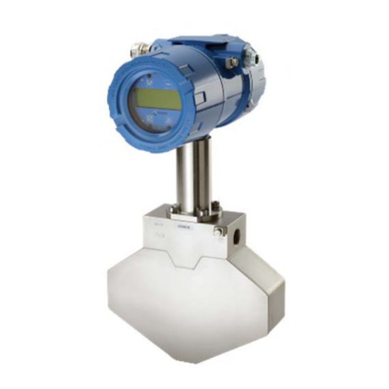
General Information 1 General Information 1.1 Features The Tricor Mass Flow Meters based on the Coriolis principle show many advantages compared to other flow meter principles: No moving parts High accuracy Simultaneous measuring of mass flow, density and temperature ... - Page 7 General Information Fig. 1: Compact version Fig. 2: Separate versions, wall mount (left) and panel mount (right)
-
Page 8: Safety
General Information 1.2 Safety 1.2.1 General Safety All statements regarding safety of operation and technical data in this manual will only apply when the unit is operated correctly in accordance with this manual. The data for Ingress Protection will only apply when all connectors are caped properly with the corresponding counterpart with the same or better IP rating. -
Page 9: Warnings In This Manual
General Information 1.2.3 Warnings in this manual NOTE: Notes provide important information for the correct usage of the equipment. If the notes are not observed, a malfunction of the equipment is possible. WARNING! Warnings provide very important information for the correct usage of the equipment. Not observing the warnings may lead to danger for the equipment and to danger for health and life of the user... -
Page 10: Ordering Codes And Accessories
D = 24V DC M = mains (90 - 264V AC) 00X0 options (S=none) 000X Cable length Housing "E": S=3m, other lengths contact KEM A= junction box, separate cable required Housing "L": N = no cable included code Ex-protection Ex-protection... - Page 11 M = 90 - 264V AC Z=not used C00X options (S=none) code Ex-protection Ex-protection empty no Ex-protection 028k Example: 028k SGSS . EADS - Please ask KEM or your nearest dealer for the possible combinations and the best solution for your application.
-
Page 12: Accessories
General Information 1.3.2 Accessories Ordering Code Description (Contact KEM) Connecting Cable TCM TCE80xx-L-* TRD8001 Additional remote display for the compact version HSA96 DIN Rail Adaptor for TCE80**-L-* IPS9-14 Protective front cover IP65 for TCE80**-L-* 1.4 Measuring Principle TCM Two parallel flow tubes inside the TCM low meter are vibrating at their resonant frequency in opposite direction. -
Page 13: Getting Started
Getting Started 2 Getting started 2.1 Unpacking Verify that you have received the following items: When you ordered a compact version: TCMxxxx… with mounted electronics User’s manual When you ordered a remote version TCMxxxx…(without electronics) TCE80xx… ... -
Page 14: Operating Elements
Getting Started 2.2 Operating Elements 2.2.1 TCE80xx-E, TCE80xx-W and compact version Fig. 4: Operating Elements of TCE80xx-E (right), TCE80xx-W (left) and compact version 1 = Pushbutton “P”, activates / selects the different menus and confirms the settings 2 = LED “OK”, flashes green when there is no error 3 = LED “ERR”, flashes red when an error occurs 4 = Display 5 = Pushbutton “Info”, normal: selects the error menu, SETUP: softkey... -
Page 15: Tce80Xx-S
Getting Started 2.2.2 TCE80xx-S Fig. 5: Operating Elements of TCE80xx-S 1 = Pushbutton “P”, activates / selects the different menus and confirms the settings 2 = LED “OK”, flashes green when there is no error 3 = LED “ERR”, flashes red when an error occurs 4 = Display 5 = Pushbutton “Info”, normal: selects the status menu, SETUP: softkey 6 = Pushbutton “Display”, normal: toggles the display, SETUP: softkey... -
Page 16: Tce80Xx-L
Getting Started 2.2.3 TCE80xx-L-* Fig. 6: Operating Elements of TCE80xx-L-*-Ex 1 = Pushbutton “P”, activates / selects the different menus and confirms the settings 2 = LED “OK”, flashes green when there is no error 3 = LED “ERR”, flashes red when an error occurs 4 = Display 5 = Pushbutton “Info”, normal: selects the status menu, SETUP: softkey 6 = Pushbutton “Display”, normal: toggles the display, SETUP: softkey... -
Page 17: Tcmxxxx
Getting Started 2.2.4 TCMxxxx-… (remote version) Fig. 7: Operating Elements TCM 1 = Locking screw for screw type terminals 2 = Cable gland for cable to the TCE 3 = Fluid output, flange / thread as ordered 4 = Screw for protective ground (TCM0325 through 3100 only) 5 = Fluid input, flange / thread as ordered 6 = M6 mounting threads (back side, option, TCM0300 through 3000 only) -
Page 18: Pin Assignments
Getting Started 2.3 Pin Assignments 2.3.1 Compact or wall mount version standard housing Fig. 8: Electrical terminals TCE80xx-W and compact version 1 = Terminal screw for protective ground 2 = Switch for terminating resistor for the RS485 interface 3 = Terminal block for interface (RS485 and / or FF) 4 = Terminal block power supply 5 = Terminal block for I/O signals... - Page 19 Getting Started TCE Terminal connections + I1 current loop 1 positive terminal - I1 current loop 1 negative terminal + I2 current loop 2 positive terminal - I2 current loop 2 negative terminal F out Frequency / pulse output CTL OUT Control output CTL IN Control input...
-
Page 20: Tce80Xx-E And Wall Mount Version
Getting Started 2.3.2 TCE80xx-E and wall mount version Fig. 9: Electrical terminals TCE80xx-E-*-Ex and compact version 1 = Terminal screw for protective ground 2 = Blind cover for cable opening (various numbers and positions) 3 = Cable gland (various numbers and positions) 4 = Terminal block for digital I/O signals (U = 250V DC) 5 = Terminal block power supply (U... - Page 21 Getting Started TCE Terminal connections Terminals with U = 30V DC + I1 current loop 1 positive terminal - I1 current loop 1 negative terminal + I2 current loop 2 positive terminal - I2 current loop 2 negative terminal PE / COM Common (for pins 21 and 22) connected to PE - RS485 RS485 negative line...
-
Page 22: Panel Mount Version Tce80Xx-S
Getting Started 2.3.3 Panel mount version TCE80xx-S Fig. 10: Electrical terminals TCE80xx-S 1 = Sliding switch for activating the 120Ω terminal resistance for RS-485 2 = Cage clamp terminals for interface RS-485 3 = Cage clamp terminals for interface foundation field bus 4 = Connector to the meter, D-Sub 9, female 5 = Cage clamp terminals for power supply 6 = Cage clamp terminals for digital I/O signals... - Page 23 Getting Started TCE Terminal connections + I1 current loop 1 positive terminal - I1 current loop 1 negative terminal + I2 current loop 2 positive terminal - I2 current loop 2 negative terminal F out Frequency / pulse output CTL OUT Control output CTL IN Control input...
-
Page 24: Panel Mount Version Tce80Xx-L-*-Ex
Getting Started 2.3.4 Panel mount version TCE80xx-L-*-Ex Fig. 11: Electrical terminals TCE80xx-L-*-Ex 1 = Sliding switch for activating the 120Ω terminal resistance for RS-485 2 = Terminal blocks for interface (U = 30V DC) 3= Terminal blocks for analog I/O signals (U = 30V DC) 4 = Terminal block for power supply (U = 250V DC) - Page 25 Getting Started TCE Terminal connections Terminals with U = 30V DC + I1 current loop 1 positive terminal - I1 current loop 1 negative terminal + I2 current loop 2 positive terminal - I2 current loop 2 negative terminal Common (for pins 21 and 22) connected to PE - RS485 RS485 negative line +RS485...
-
Page 26: Quick Start
Getting Started 2.4 Quick start WARNING! As for safety and accuracy reasons many precautions must be taken, read chapter 3 carefully before installing the unit! In case the unit has only to be operated without flow for testing or learning purpose, the following connections have to be made (see chapter 3.2): ... -
Page 27: Control Menu
Getting Started 2.4.3 CONTROL Menu In the CONTROL menu all configurations can be made. This includes configuration of the analogue and digital outputs, customizing the display and other settings. The menu itself is self-explaining, the function of the softkeys (5, 6, 7) is indicated in the display above the pushbutton. -
Page 28: Installation
Installation 3 Installation 3.1 Mechanical In accordance with this manual the user should select the installation position which fits the application best. To ensure the highest degree of accuracy and repeatability, care should be taken to affix the Tricor products in a stable process site and minimize the amount of vibration in the installation environment 3.1.1 Installation Guidelines... -
Page 29: Horizontal Installation
Installation 3.1.2 Horizontal Installation The horizontal installation is the recommended installation. If the medium might contain solid particles, mount the meter as in position “A”, in all other cases as in position “B”. Fix the meter to a solid, non-vibrating surface as close to the meter as possible. With the TCM0325 through TCM3100 this could be done via the optional mounting threads. -
Page 30: Installation In A Drop Line
Installation 3.1.4 Installation in a Drop Line The diamond shaped TCM0325 through TCM3100 should not be mounted vertically at all. All other meters can be mounted vertically, but mounting in a drop line is only allowed, if an orifice and the closing valve are located below the meter for making sure, that neither during operation nor after closing the valve the meter will run empty. -
Page 31: Mechanical Installation Of The Electronics (Remote Versions)
Installation 3.1.6 Mechanical Installation of the electronics (remote versions) TCE80xx-W The wall mount unit is to be mounted on the wall with 2 screws with 5mm diameter, about 40mm apart. For exact dimensions refer to chapter 7.3.4 TCE80xx-E The wall mount unit is to be mounted on the wall with 2 to 4 screws with 5mm diameter, 45mm apart. For exact dimensions refer to chapter 7.3.4 If the mounting point should be located behind the TCE80xx instead beside, unscrew the 4 screws fixing the bracket to the housing, fix the bracket to the wall and reaffix the housing to the bracket. -
Page 32: Electrical Installation
Installation 3.2 Electrical installation Make sure that the unit is properly mounted and the process input and output are connected before making the electrical connections. This unit must be grounded. The TCE requires a regulated DC power supply of 24V ±20% or a mains voltage of 100 to 240V AC, depending on the version. -
Page 33: Connecting Tce And Tcm
Installation 3.2.1 Connecting TCE and TCM With the remote version the TCE and TCM must be connected before making the other electrical installations. If no TCM is connected to the TCE, the TCE will only show an error message after power on. Connecting the cable to the TCM Open the junction box of the TCM. -
Page 34: Electrical Installation Of Panel Mount Version
Installation NOTE: In bigger installations a separate PE connection with a high cross section (> 1.5mm²) is recommended for avoiding high equalizing currents in the shield. Connect the individual cables to the cage clamp terminals as required. The Ex versions have self-opening terminals. Push the cable end sleeves into the terminals. There is no tool required to connect the cables. - Page 35 Installation TCE8000 Fig. 16: Wiring diagram for power connections, DC operation Terminal Description Positive supply Voltage, 24V ±20%, referred to pin 51 Ground potential for supply voltage Protective ground The ground terminals 8 and 51 are internally connected together. Ground and protective ground are internally connected via a 1kΩ resistor. The resistor will thermally withstand a potential difference of up to 30V between PE and GND but for proper operation this difference should be limited to 3.2.4.2 100 to 240V AC Mains Supply...
- Page 36 Installation TCE8000 Fig. 17: Wiring diagram for power connections, AC operation Terminal Description Mains life, referred to pin 51 Mains neutral Protective ground The ground terminal 8 is not connected to terminal 91. 3.2.4.3 DC and AC supply The TCE80xx-S-xBxx or TCE80xx-L-xBxx can be connected to a 24V DC and a mains supply simultaneously. The unit will operate properly as long as one of the 2 supplies is present.
-
Page 37: Connecting The Control Inputs And Outputs
Installation 3.2.5 Connecting the control inputs and outputs TCE8000 Fig. 18: Wiring diagram for digital I/O connections Terminal Description Frequency output, active, referred to pin 8 Status output, active, referred to pin 8 Control input, active high, referred to pin 8 Ground potential for digital I/O- pins. -
Page 38: Connecting The Analog Outputs
Installation The control input requires a high voltage of minimum 6.5V and a minimum input current of 0.1mA. The ground terminals 8 and 51 are internally connected together. Ground and protective ground are internally connected via a 1kΩ resistor. The resistor will thermally withstand a potential difference of up to 30V between PE and GND but for proper operation this difference should be limited to 3.2.6 Connecting the analog outputs... -
Page 39: Ex Installation
Installation 3.3 Ex Installation WARNING! In hazardous locations all installations must only be carried out by qualified personnel! Switch off all power supplies before installing or uninstalling the unit in hazardous locations! 3.3.1 Locating the Compact Version The TCM***-**-****-E*** -Ex is explosion proof with EX d for the electronics and Ex i for the meter. The inputs and outputs are not power limited and must not be used to drive intrinsically save circuits WARNING! Never open any cover of the electronics in hazardous locations with any supply or I/O circuits alive! -
Page 40: Power Supply And Grounding
TCM! WARNING! If more than 30V have been applied to any of the analog output pins, the unit must be returned to KEM for repair as the safety barrier might be destroyed! For the circuit diagrams and the general description refer to chapter 3.2.6. -
Page 41: Manual Operation
Manual Operation 4 Manual Operation 4.1 Power On Sequence and Principles of Manual Control The power up sequence gives the following information, each for about 2 second: CORIOLIS TRICOR TCE8000 This gives the type of electronics. At the time being the types TCE8001 (low power) and TCE8011 (high power) are available. -
Page 42: Using The Magnet
Manual Operation ***……. WARNING …….*** NO ACTUAL RAM BACKUP SEE MANUAL If no key is pressed the warning will disappear automatically after 10 seconds. For further information refer to chapter 4.5.8. Now the TCE8000 switches to the measuring mode, displaying the default screen: 0.000 RATE 0.00... -
Page 43: Meter Mode
Manual Operation 4.2.1 Meter Mode A coriolis mass flow meter measures the mass flow and the density and can calculate the volume flow. For avoiding strange effects with the total values when changing the dimensions, the TCE8000 can be set up as a mass flow OR a volume flow meter. -
Page 44: Cutoff
Manual Operation 4.2.4 Cutoff As mentioned above, a mass flow meter has no natural zero and the rough data are noisy. Consequently with now flow a meter would indicate and give out continuously a small fluctuating flow. The parameter CUTOFF is used to provide a clear zero. If the calculated and filtered flow is below cutoff, the meter indicates zero, the total values remain unchanged and the outputs show zero flow as well. - Page 45 Manual Operation In ON-OFF operation with a fast rising and slowly falling flow a systematic positive error is to be expected. If the rising is slow and the falling fast, the error will be negative. WARNING! If step response is used (e.g. for good reaction to fast changing flow), checking the accuracy for the given application is strongly recommended!
-
Page 46: Measuring Mode
Manual Operation 4.3 Measuring mode 4.3.1 Function of the keys In the measuring mode all pushbuttons have a fixed function: Opens the Control Menu if pressed for about 3 seconds Reset Resets the batch counter to zero, if the function “KEY RESET” is enabled Display Toggles the display between the 2 preselected settings. -
Page 47: Offset Calibration
Manual Operation Press “Info” a second time for getting 8 internal operating parameters: Code Value Sensor voltage A in mV Sensor voltage B in mV Driver current in mA Measured Temperature in °C Oscillating frequency in Hz Totalizer value in the selected units Zero point offset in µs RS485 RS485 address... -
Page 48: Control Mode
Manual Operation 4.5 Control Mode In the control mode the TCE8000 can be adapted to the individual application. As unintentional changes of the settings might cause problems, some submenus are password protected. To enter the control mode proceed as follows: Press “P”... -
Page 49: Zero Offset Menu
Manual Operation 4.5.3 ZERO OFFSET Menu Select in the main menu MAIN MENU ZERO OFFSET DOWN EXIT Press “P”. The display shows ENTER CODE 2206 LEFT EXIT Change the indicated number with “LEFT” and “UP” to 2207 and confirm with “P”. If a wrong code is entered, the display shows “ERROR”... -
Page 50: Display Menu
Manual Operation 4.5.4 DISPLAY Menu Select in the main menu MAIN MENU DISPLAY DOWN EXIT Press “P”. The display shows DISPLAY MENU FLOW DISPLAY DOWN EXIT The following submenus are available: FLOW DISPLAY: Setting the flow units, the flow decimal point and a flow filter for the display. TOTAL DISP: Setting the total and batch units and the total and batch decimal point. - Page 51 Manual Operation FLOW UNITS SET FLOW DISPLAY SELECT MASS UNITS FLOW UNITS P DOWN EXIT DOWN EXIT Depending on the selected meter mode (mass flow meter or volume flow meter) the display indicates “SELECT MASS UNITS” or “SELECT VOLUME UNITS” and provides correspondingly only mass or volume units. The meter mode can only be changed in the SETUP menu (see chapter 4.5.6.1) The following units (volume or mass per time) can be selected: time-Unit...
- Page 52 Manual Operation NOTE: The display filter only filters the value in the display for providing a more stable reading. It has no influence on the outputs. As the display filter is additional to the global filter, the display can never react faster than the outputs. Use the keys “RIGHT”...
- Page 53 Manual Operation TOTAL DP SET TOTAL DISPLAY SELECT TOTAL DP TOTAL DP 000.0 P DOWN EXIT LEFT EXIT Use the key “LEFT” to select the desired decimal point position and confirm with “P” or skip with “E”. 4.5.4.3 DENS DISPLAY menu In the submenu “DENS DISPLAY”...
- Page 54 Manual Operation 4.5.4.5 DISP MODE menu In the submenu “DISP MODE” the display mode can be set. DISPLAY MENU SET DISPLAY MODE DISP MODE DISPLAY 1 P DOWN EXIT DOWN EXIT Use the keys “UP” and “DOWN” to select the desired submenu and confirm with “P” or skip with “EXIT”. The following submenus are available: DISPLAY 1: Setting the content of display view 1.
- Page 55 Manual Operation If “DUAL LINE” was selected, the display shows SELECT LINE2 VALUE RATE DOWN EXIT Use the keys “UP” and “DOWN” to select the desired value and confirm with “P” or skip with “EXIT”. The unit returns to the display mode menu. DISPLAY 2 See DISPLAY 1 BACKLIGHT...
-
Page 56: Setup Menu
Manual Operation 4.5.5 SETUP Menu In the SETUP menu all settings can be made to adapt the meter to the individual requirements. Select in the main menu MAIN MENU SETUP DOWN EXIT Press “P”. The display shows ENTER CODE 2206 LEFT EXIT Change the indicated number with “LEFT”... -
Page 57: Setup Parameter Menu
Manual Operation 4.5.6 SETUP PARAMETER menu In the submenu SETUP / PARAMETER all user settable internal parameter can be set for adjusting the unit for a given application. SETUP MENU PARAMETER MENU PARAMETER METER MODE P DOWN EXIT DOWN EXIT Use the keys “UP”... - Page 58 Manual Operation PARAMETER MENU FLOW FILTER 0-99.9s FLOW FILTER 1.00000 P DOWN EXIT RIGHT EXIT Use the keys “RIGHT” and “UP” to select the desired value and confirm with “P” or skip with “EXIT”. The display returns to the setup parameter menu. 4.5.6.3 CUT OFF menu In the submenu “CUT-OFF”...
- Page 59 Manual Operation 4.5.6.5 RESET KEY menu In the submenu “KEY-RESET” the pushbutton “Reset” can be enabled or disabled. If the pushbutton Reset is active, it can be used to reset the batch counter. PARAMETER MENU SELECT RES.KEY MODE RESET KEY RES.
-
Page 60: Setup In/Outpus Menu
Manual Operation 4.5.6.8 FAULT TIME menu In the submenu “FAULT TIME” the reaction time of the TCE8000 in case of an error can be defined. The fault on delay time is the time an error must be present, until the red LED lights up and the error output signal is activated. - Page 61 Manual Operation 4.5.7.1 FREQ OUT menu In the submenu “FREQ OUT” the frequency output can be configured. The frequency output has 2 operating modes: FREQUENCY: A frequency proportional to the actual flow is generated. If a negative flow must be given out as well, the control output can be used as sign. Frequencies between 0.5Hz and 10kHz can be generated in this mode.
- Page 62 Manual Operation TOTAL COUNT FREQ OUT MENU SELECT VALUE TOTAL COUNT 0.10000 P KILO DOWN EXIT RIGHT EXIT Use the keys “RIGHT” and “UP” to select the desired step value and confirm with “P” or skip with “EXIT”. 4.5.7.2 CONTROL OUT menu In the submenu “CTRL OUT”...
- Page 63 Manual Operation 4.5.7.3 ANALOG OUT menu In the submenu “ANALOG OUT” the 4 – 20mA outputs can be configured. Each analog output can show one of the following 4 parameters: FLOW: The output current is proportional to the actual flow. DENSITY: The output current is proportional to the actual density.
- Page 64 Manual Operation 4.5.7.4 CONTROL IN menu In the submenu “CTRL IN” the control input can be configured. The control input has 2 operating modes: RESET BATCH: If a high level is applied to the input, the batch counter is reset to 0. This mode must be selected, if the control output is to be used as a batch output and / or if one of the analog outputs is to be used as batch output EXTERNAL ZERO:...
-
Page 65: Setup Data Configuration Menu
Manual Operation CURRENTLY HART NOT AVAILABLE, READ THE MANUAL FOR MORE INFO Confirm with “OK” and select an implemented interface. 4.5.8 SETUP DATA CONFIGURATION menu In the submenu SETUP / DATA CONFIG the current setting can be stored to the backup memory and the stored settings can be recalled SETUP MENU DATA CONFIG MENU... -
Page 66: Setup Reset Total Menu
Manual Operation 4.5.8.2 RECALL DATA menu In the submenu “RECALL DATA” the old settings are reloaded from the backup memory. Reloading the old settings is recommended if after bigger changes in the setup the unit does not work properly any more. NOTE: Backup data overwritten with “SAVE DATA”... -
Page 67: I/O-Test Menu
Manual Operation 4.5.10 I/O-TEST Menu In the I/O-TEST menu all inputs and outputs can be tested. Select in the main menu MAIN MENU I/O-TEST DOWN EXIT Press “P”. The display shows ENTER CODE 2206 LEFT EXIT Change the indicated number with “LEFT” and “UP” to 2207 and confirm with “P”. If a wrong code is entered, the display shows “ERROR”... - Page 68 Manual Operation If “EXIT” is pressed, the display returns to the I/O-TEST menu. 4.5.10.2 CTRL OUT menu In the submenu “CTRL OUT” a low or high level can be applied to the output. I/O-TEST MENU SELECT OUTPUT LEVEL ! CTRL OUT P ...
-
Page 69: Service Menu
Manual Operation 4.5.11 SERVICE Menu The “SERVICE” menu is used to calibrate the meter and to recall the original factory settings. For a description of the menu refer to chapter 6.4. -
Page 70: Remote Operation
If more than 30V have been applied to any of the RS-485 terminals, the unit must be returned to KEM for repair as the safety barrier might be destroyed! 5.1.3 RS485 Interface Protocol For setting up a communication refer to the command list available from KEM. -
Page 71: Hart
WARNING! If more than 30V have been applied to any of the analog output terminals, the unit must be returned to KEM for repair as the safety barrier might be destroyed! 5.2.3 HART Interface Protocol For getting the newest DD file contact KEM. -
Page 72: Foundation Fieldbus
WARNING! If more than 30V have been applied to any of the FF terminals, the unit must be returned to KEM for repair as the safety barrier might be destroyed! 5.3.3 FF Interface Protocol For getting the newest DD file contact KEM. -
Page 73: Service And Maintenance
In case of abrasive or sedimenting media however it is recommended to return the measuring system to KEM after 8,000 hours of operation for re-calibration and pressure test. This interval may be shorter when the medium is extremely abrasive or sedimenting. -
Page 74: Changing The Fuses
Replace the fuse and reclose the unit. 6.3.3 Changing the fuses with the Ex versions With the Ex versions the fuses are part of the safety barriers and must only be exchanged by KEM or by personnel authorized by KEM. -
Page 75: Calibration
Service and Maintenance 6.4 Calibration In the calibration menu the flow, density and temperature measurement of the TCE8000 can be calibrated. Press “P” for about 3 seconds The display shows: MAIN MENU ZERO OFFSET DOWN EXIT Use the key “UP” or “DOWN” to select MAIN MENU SERVICE DOWN... -
Page 76: Temperature Calibration
Service and Maintenance 6.4.1 Temperature Calibration For calibrating the temperature reading of the TCE8000, the medium temperature must be well known. Before starting the calibration make sure that the temperature reading has been stable for several minutes for making sure that the medium temperature and the temperature of the temperature sensor are the same. - Page 77 Service and Maintenance DO YOU WANT TO PROCEED CALIBRATION? Start the calibration with “YES” or skip with “NO”. When “YES” was pressed, the display shows AIR-TEMP: 23.0°C FREQUENCY: 141.5 Hz DENSITY: 1.4 G/L Confirm with “OK”. The display returns to the AIR CALIBRATION menu. MANUAL MODE AIR CALIBRATION MENU ENTER AIR TEMP:...
-
Page 78: Water Density Calibration
Service and Maintenance 6.4.3 Water Density Calibration NOTE Make sure that the temperature reading is calibrated before starting the water calibration. The high end calibration of the density measurement is normally done with tubes filled with water, but any other liquid with well-known density can be used as well. In the automatic mode the unit performs an automatic calibration, assuming that the tubes are filled with water. -
Page 79: Flow Calibration
Service and Maintenance MANUAL MODE WATER CALIBRATION MENU ENTER WATER TEMP: MANUAL P 23.0 °C DOWN EXIT RIGHT EXIT Use the keys “RIGHT” and “UP” to set the reference temperature and confirm with “P” or skip with “EXIT”. The display shows ENTER WATER FREQ: 131.27 RIGHT... -
Page 80: Service
Service and Maintenance 6.5 Service The TCE8000 does not contain any user serviceable parts. In case of malfunction, please contact your nearest dealer or directly KEM. For the addresses see chapter 7.7. 6.6 Reloading Factory Settings In case the unit has been completely misadjusted for any reason, the unit can be reset to the original settings ex work. - Page 81 Service and Maintenance Start the recall process with “START” or skip with “EXIT”. If “START” is pressed, the display shows for some seconds MEMORY ACCESS After that for about 2 seconds. READY The display returns to the RECALL FACT menu.
-
Page 82: Listings
Listings 7 Listings 7.1 Warranty KEM warrants material and production for a period of 12 months after installation and start up, max. 18 months from delivery date. 7.2 Certifications and compliances Category Standards or description EC Declaration of Conformity - Meets intent of Directive 2004 / 108 / EEC for Electromagnetic Compatibility. - Page 83 Listings Category Standards or description EC Declaration of Conformity – Compliance is given to the following specification as listed in the Official Journal Low Voltage of the European Communities: Low Voltage Directive 2006/95/EEC EN 61010-1 / 2002 Safety requirements for electrical equipment for measurement control and laboratory use.
-
Page 84: Technical Data
Listings 7.3 Technical Data 7.3.1 Technical Data TCM Transducer TCM0325 TCM0650 TCM1550 TCM3100 TCM5500 TCM7900 TCM28k TCM65k Max. flow (kg/h) 1500 3000 5500 7900 28 000 65 000 Min. flow (kg/h) Max. flow (lb/min) 11.0 22.0 55.0 1030 2390 Min. flow (lb/min) 0.11 0.22 0.55... -
Page 85: Ex Data Tcm Transducer
Listings 7.3.2 Ex Data TCM Transducer TCM0325 TCM0650 TCM1550 TCM3100 TCM5500 TCM7900 TCM28k TCM65k Driver coil Vmax (V) Imax (mA) Pmax (W) 0.75 Ri (Ohm) L (mH) 2.77 1.85 C (nF) << 1 << 1 << 1 Sensor coil Vmax (V) Imax (mA) Pmax (W) 0.75... -
Page 86: Technical Data Tce 8000 Transmitter
Listings 7.3.3 Technical Data TCE 8000 Transmitter General Display: Graphic, 132 x 32 dot Supply voltage: 24 VDC, ± 20% Programming: via front keyboard Interface: RS 485, option HART or Foundation Fieldbus EMC: according to EN 61000-6-4 and EN 61000-6-2 Power consumption: max. - Page 87 Listings Analog Outputs Two current outputs: 4-20 mA passive, two-wire, isolated Resolution: 14 bit Linearity: ± 0.05% of full scale Temperature drift: 0.05% per 10K Load: < 620 Ω (at 24V supply) Output value: flow rate, job total, density or temperature Pulse Output Frequency range: 0.5 -10,000 Hz...
-
Page 88: Ex Data Tce Transmitter
Listings 7.3.4 Ex Data TCE Transmitter Barrier output TCE8001 TCE8011 TCE8021 Driver coil hot side Vmax (V) Imax (mA) Pmax (W) 0.42 1.12 1.12 Driver coil cold side Vmax (V) Imax (mA) Pmax (W) Sensor coil Vmax (V) Imax (mA) Pmax (W) 0.08 Pt1000 driver... -
Page 89: Dimensional Drawings (Mm)
Listings 7.3.5 Dimensional Drawings (mm) Compact versions Fig. 20: Dimensions TCM0325-**-****-C*** through TCM3100-**-****-C*** Fig. 21: Dimensions TCM0325-**-****-E*** through TCM3100-**-****-E***... - Page 90 Listings Fig. 22: Dimensions TCM5500-**-****-C*** through TCM65k-**-****-C*** Fig. 23: Dimensions TCM5500-**-****-E*** through TCM65k-**-****-E***...
- Page 91 Listings Sensor Dimensions Type TCM0325 G ½ ” TCM0650 G ½ ” TCM1550 G ½ ” TCM3100 G ½ ” Type TCM5500 TCM7900 TCM28k TCM65k *) See order code or ask KEM Electronics Dimensions Type Housing “C” Housing “E”...
- Page 92 Listings Remote meter Fig. 24: Dimensions TCM***-**-****-A*** Remote wall-mounted electronics Fig. 25: Dimensions TCE8000-W-****...
- Page 93 Listings Fig. 26: Dimensions TCE8000-E-**** (except ***A) Fig. 27: Dimensions TCE8000-E-***A...
- Page 94 Listings Remote panel-mounted housings Fig. 28: Dimensions TCE8000-S-**** The required cutout for the panel is 92mm +0.8/-0mm x 92mm +0.8/-0mm. The maximum thickness of the panel is 2mm. Fig. 29: Dimensions TCE8000-L-**** The required cutout for the panel is 138mm +1.0/-0mm x 92mm +0.8/-0mm. The maximum thickness of the panel is 2mm.
-
Page 95: Weee And Rohs
Listings 7.4 WEEE and RoHS The unit described herein is not subject to the WEEE directive and the corresponding national laws. At the end of life forward the unit to a specialized recycling company and do not dispose it off as domestic waste. -
Page 96: List Of Tables
Listings 7.6 List of tables ......................... 33 ONNECTIONS XXXX .......................... 46 RROR ODES ...................... 47 IST OF SERVICE PARAMETERS ........................... 47 IST OF UNIT INFO... -
Page 97: Addresses
Listings 7.7 Addresses Headquarter Küppers Elektromechanik GmbH Liebigstraße 5 DE-85757 Karlsfeld Germany Tel.: +49 8131 593910 info@kem-kueppers.com www.kem-kueppers.com... - Page 98 Contact Copyright KEM, Subject to change without notice, ES. Rev 002-23/01/2012...
Need help?
Do you have a question about the TRICOR TCE80 -E Series and is the answer not in the manual?
Questions and answers