
Related Manuals for KEM TRICOR CLASSIC Series


Summary of Contents for KEM TRICOR CLASSIC Series
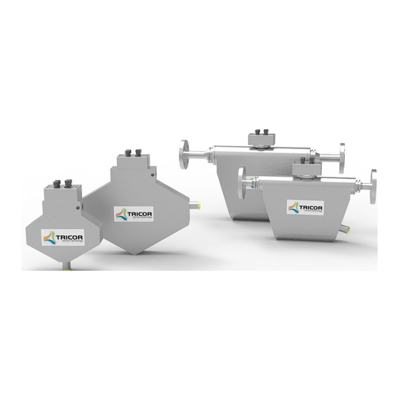
- Page 1 CLASSIC Serie | Instruction Manual TRICOR® Coriolis Mass Flow Meter with TCE 6000 transmitter...
- Page 2 Version Manual-Version TCM_E60_CLASSIC_M_EN_190215_E012 SW-Version This manual is valid for Main SW: Mv3.40 and higher Display SW: Dv3.40 and higher CLASSIC Series | Instruction Manual | Version: TCM_E60_CLASSIC_M_EN_190215_E012...
-
Page 3: Table Of Contents
Index Index GENERAL INFORMATION ....................5 1.1. Features ..............................5 1.2. Safety ..............................6 1.2.1. Warnings ..............................6 1.2.2. General Safety ............................6 1.2.3. Special Requirements for Ex Installation ....................8 1.2.4. Handling of the Bursting Disc ......................10 1.3. Model Key and Accessories ......................... - Page 4 Index 4.2.2. Zero Point Adjustment ......................... 25 4.2.3. Flow filter ............................. 26 4.2.4. CUT OFF ............................... 26 4.2.5. STEP RESPONSE............................ 26 4.2.6. Mutual Influences of Configuration Parameters ................. 27 4.3. Operating Modes of the Inputs and Outputs ..................28 4.3.1. Frequency Output ..........................28 4.3.2.
-
Page 5: General Information
General Information General Information 1.1. Features The TRICOR CLASSIC Mass Flow Meters based on the Coriolis principle show many advantages compared to other flow meter principles: • Cost-effective, not calibrated, but with excellent repeatability Higher accuracy possible with customer-specific calibration •... -
Page 6: Safety
WARNING! There is a risk of parts being ejected if the bursting disc ruptures; sufficient protection such as covers must be provided. Take the device out of operation and contact KEM Küppers Elektromechanik GmbH. WARNING! Make sure that the bursting disc is not damaged when mounting a tube or connecting elements on the housing. - Page 7 General Information WARNING! The maximum permissible pressure must not be exceeded due to pressure surges. Risk of injury or poisoning. The maximum permissible operating pressure depends on the device version, pressure limit and temperature range. The device may be damaged if the operating pressure is exceeded. Hot, toxic and corrosive process media may be released.
-
Page 8: Special Requirements For Ex Installation
General Information WARNING! External stresses and loads Damage to the device due to severe external stresses and loads (thermal expansion or pipe strain, for example). The process medium may be released. Risk of the ejection of components and the discharge of medium under high pressure. - Page 9 General Information WARNING! Use in areas exposed to explosion hazards There is a risk of explosion in areas exposed to explosion hazards. Special requirements apply here with regard to the device location and installation. See “Electrical installation” (Sections 3.3 and 3.4). WARNING! Explosion hazard.
-
Page 10: Handling Of The Bursting Disc
WARNING! There is a risk of parts being ejected if the bursting disc ruptures; sufficient protection such as covers must be provided. Take the device out of operation and contact KEM Küppers Elektromechanik GmbH. WARNING! Make sure that the bursting disc is not damaged when mounting a tube or connecting elements on the housing. -
Page 11: Model Key And Accessories
General Information 1.3. Model Key and Accessories 1.3.1. Model Key XXXX Process connections See TCM datasheet Mechanical options Medium Temperature range: -40 °C…+100 °C [-40 °F…+212 °F[ Pressure range Standard pressure Mechanical Design Standard Face to face length Standard (other lengths on request) Electronic options Execution Compact version TCE 6000... -
Page 12: Tcm Measuring Principle
General Information 1.4. TCM Measuring Principle Two parallel tubes inside the TCM vibrate at their resonant frequency in opposite directions. Any mass flow passing through the tubes will delay the vibration at the incoming side and accelerate the vibration at the outgoing side. -
Page 13: Getting Started
TCM **** with installed transmitter • Operating instructions (printed version or www.kem- kueppers.com/downloads/bedienungsanleitungen) Inspect the device to make sure it is undamaged. Contact KEM Küppers Elektromechanik GmbH in case of damage. 2.2. Operating Elements Fig. 4: Operating Elements 1 = RS485 connection, M12, B-coded, internal thread... -
Page 14: Pin Assignments
Getting started 2.3. Pin Assignments I/O 5-pin (standard version “FSDS”) +24V DC Positive supply voltage (24 V DC) Output current 4 … 20 mA, in reference to GND Ground Frequency/pulse output CTL IN 1 Control input 1 I/O 8-pin (extended version “FFDB”) +24V DC Positive supply voltage (24 V DC) Output current 4 …... -
Page 15: Trial Run
Getting started 2.4. Trial run WARNING! Read the installation information in Section 3 carefully before installing the device! When the device is only operated briefly with no flow for testing or familiarisation, establishing the following connections as a minimum is sufficient (see Section 3.3): •... -
Page 16: Installation
Installation Installation 3.1. Important Installation Guidelines Coriolis Mass Flow Meters measure the flow by accelerating the medium transverse to the flow direction and measuring the effect of the inertial force. For optimum results, the device has to be decoupled from external vibrations and the medium must be homogeneous. -
Page 17: Mechanical Installation
The manufacturer can assist you with the selection of sensor components that are wetted by the process medium. The operating company is responsible for selecting the components. KEM Küppers Elektromechanik GmbH assumes no liability for faults or failures due to incompatible materials. -
Page 18: Requirements For The Installation Location
Avoid exposing the device to external stresses and loads. 3.2.2. Requirements for the Installation Location TRICOR Classic series flowmeters have the protection class IP65 as standard. The devices are not suitable for outdoor installation. Process pressure and media temperature Make sure that the process pressure (PS), media temperature (TS) and ambient temperature do not exceed or fall below the value ranges specified on the type plate/device label. -
Page 19: Horizontal Installation
Installation Direct sunlight Protect the device from direct sunlight to prevent overheating or materials getting brittle due to UV exposure. Make sure that the ambient temperature does not exceed or fall below the permissible limits. Observe the information in the technical data (see Section 7.3). WARNING! Use in areas exposed to explosion hazards. -
Page 20: Vertical Installation
Installation 3.2.4. Vertical installation The TCM 0325 through TCM 3100 should not be installed vertically due to the lozenge shape of the tubes – unless you are certain that the medium contains neither gas bubbles nor solids. All other sensors (TCM 5500 – 230K) can be installed vertically. This is the recommended installation position if the medium contains gas bubbles and/or solids. -
Page 21: Critical Installations
Installation 3.2.6. Critical installations If gas bubbles are expected in the measured medium, the measuring device must not be installed at the highest point of the pipe system. Otherwise, accumulations of gas and therefore faulty measurements must be expected regardless of the installation position of the measuring device itself (A). If solids are expected in the measured medium, the measuring device must not be installed at the lowest point of the pipe system. -
Page 22: Fig. 9: Tce 6000 Connection Diagram
Installation NOTE: A separate protective conductor connection with a cross-section larger than 1 mm² is recommended in larger systems to avoid stray electric currents in the cable shield. Wiring diagram +24V DC Positive supply voltage (24 V DC) Output current 4 … 20 mA, in reference to GND Ground Frequency/pulse output CTL IN 1... -
Page 23: Power Supply And Grounding
Installation 3.3.1. Grounding ower Supply and The TCE 6000 requires a regulated power supply of 24 V DC. The supply input of the TCE is protected by an internal fuse. To protect against fire due to a short-circuit in the supply cable, the power supply output must be protected by a fuse with a tripping current that does not exceed the current carrying capacity of the cable. -
Page 24: Analogue Outputs
Installation 3.3.3. Analogue Outputs The TCE 6000 has one active 4 … 20mA output (earthed). The maximum load resistor depends on the supply voltage. ���� ( ������������ ) = For a certain supply voltage, the maximum load resistor is calculated as: ����... -
Page 25: Manual Operation
Manual Operation Manual Operation 4.1. Manual Control The TCE 6000 has no control elements or displays. Operation and configuration is exclusively via software remote control. 4.2. Setup Guidelines The TCM Mass Flow Meters are configured for normal applications at the factory. Aside from regular zero point adjustment as needed, no further optimisations are required for most applications. -
Page 26: Flow Filter
Manual Operation 4.2.3. Flow filter The raw data of a Mass Flow Meter are noisy. Therefore, the calculated flow rate values have to be filtered for a stable indication. to drop to ����/���� = ����/2,72 at the output after a jump at the input from a value x to 0. A longer time results in The filter in the TCE 6000 is adjusted via a time constant. -
Page 27: Mutual Influences Of Configuration Parameters
Manual Operation When the flow is constant or changes gradually, “STEP RESPONSE” should be deactivated with the setting 99% (default value). If “STEP RESPONSE” is needed, the best setting must be determined experimentally. The best value for ON/OFF operation is about 50% of the ON value. If the value chosen for “STEP RESPONSE”... -
Page 28: Operating Modes Of The Inputs And Outputs
Manual Operation 4.3. Operating Modes of the Inputs and Outputs The inputs and outputs can be configured for different applications. Software remote control via an interface cable is required to change the settings. 4.3.1. Frequency Output The frequency output has two possible operating modes: FREQUENCY (default value): A frequency proportional to the flow is output. -
Page 29: Control Input
Manual Operation DENSITY: The current is proportional to the actual density. TEMPERATURE: The current is proportional to the actual temperature. BATCH COUNT: The current is proportional to the actual “BATCH” value. This operating mode is only available if the control input is configured as “RESET BATCH”. The reference values for 4 mA and 20 mA can be freely selected. -
Page 30: Remote Control
A standard USB A to MINI USB cable can be used to temporarily connect the USB interface. NOTE: The USB A to USB M12 cable from KEM Küppers Elektromechanik GmbH is required for a stationary connection in an automated system in order to guarantee the specified IP protection class. -
Page 31: Service And Maintenance
Service and Maintenance Service and Maintenance 6.1. Troubleshooting If the TRICOR Mass Flow Meter is not working properly, please check the following points: Does not operate All cables properly connected? Connect missing cables Power supply on? Turn on the power supply ... -
Page 32: Service And Maintenance
Service and Maintenance Service and Maintenance The TRICOR CLASSIC Mass Flow Meters and the TCE 6000 transmitter do not require regular maintenance. An inspection and recalibration every 5 years is recommended for optimum measurement results. When abrasive or fouling process media are used, the inspection intervals should be considerably shorter in order to monitor the measurement results and, where applicable, the pressure resistance of the measuring device. -
Page 33: Calibration
TCE 6000. 7.1.1. Recalibration KEM Küppers Elektromechanik GmbH and AW-Lake Company will recalibrate the sensor in Germany or the USA. The following configuration types are offered as standard depending on the configuration: •... -
Page 34: Cleaning
7.3. Service The TCE 6000 does not contain parts that can be exchanged or repaired by the user. Please contact KEM/AWL or the nearest distributor in case of a malfunction. 7.4. Resetting to Factory Settings If the device settings are entirely incorrect for some reason, the device can be reset to the original factory settings. -
Page 35: Important Notices
8.1. Warranty The terms of guarantee (general business terms and conditions) are available on the website of KEM Küppers Elektromechanik GmbH (www.kem-kueppers.com) or, for America, the website of AW Lake Company (www.aw-lake.com). 8.2. Certifications and Compliances Category Standards or description EU Declaration of Compliant with Directive 2014/30/EU for electromagnetic compatibility. -
Page 36: Technical Data
Important Notices 8.3. Technical Data 8.3.1. TCM transmitter – Technical Data for Liquids 0325 0650 1550 3100 5500 7900 028K Max. flow (kg/h) 1,550 3,100 5,500 7,900 28,000 Max. flow (lb/min) 1,029 Basic accuracy, mass ±0.1% of the measured value Basic accuracy, volume ±0.15% of the measured value Reproducibility... -
Page 37: Accuracy For Liquids
Important Notices 8.3.2. Accuracy for Liquids TCM 0325 to TCM 065K Mass Flow Volume Flow CLASSIC Series | Instruction Manual | Version: TCM_E60_CLASSIC_M_EN_190215_E012... -
Page 38: Tcm Transmitter - Technical Data For Gases
Important Notices 8.3.3. TCM Transmitter – Technical Data for Gases 0325 0650 1550 3100 5500 7900 028K Nom. Flow Rate (kg/h) 5) 7) 1,430 5,100 Nom. Flow Rate (lb/min) 5) 7) Nom. Flow Rate (Nm 5) 6) 1,031 1,268 1,993 7,109 Nom. -
Page 39: Accuracy For Gases
Important Notices 8.3.4. Accuracy for Gases Mass Flow CLASSIC Series | Instruction Manual | Version: TCM_E60_CLASSIC_M_EN_190215_E012... -
Page 40: Technical Data, Tce 6000 Transmitter
Important Notices 8.3.5. Technical Data, TCE 6000 Transmitter General Supply 24V DC Voltage Programming Software interface Interface RS485 for Modbus RTU EN 61000-6-4 and EN 61000-6-2 Power consumption Max. 4 W Electrical connections M12, A-coded, external thread (I/O, power supply) M12, B-coded, internal thread (RS485, power supply) M12 MINI USB Housing material... -
Page 41: Dimensions Drawings
Important Notices 8.3.6. Dimensions Drawings Dimensional Drawing TCM 0325 to TCM 0650 Fig. 10: Dimensions TCM 0325-**-****-**** through TCM 0650-**-****-**** Dimensional Drawing TCM 1550 to TCM 3100 Fig. 11: Dimensions TCM 1550-**-****-**** through TCM 3100-**-****-**** CLASSIC Series | Instruction Manual | Version: TCM_E60_CLASSIC_M_EN_190215_E012... -
Page 42: Fig. 12: Dimensions Tcm 5500-**-****-**** Through Tcm 028K
Important Notices Dimensional Drawing TCM 5500 to 028K Fig. 12: Dimensions TCM 5500-**-****-**** through TCM 028K-**-****-**** Connection Sensor type 200 mm 61 mm 204 mm 260 mm 460 mm TCM 5500, 7900 on request [7.87 in] [2.40 in] [8.03 in] [10.24 in] [18.11 in] 217 mm... -
Page 43: Weee And Rohs
List of Figures 8.4. WEEE and RoHS The devices described here are not subject to the WEEE Directive and the corresponding national laws. Dispose of used devices properly and not in household waste. The devices described here fully comply with the RoHS Directive. List of Figures Fig. - Page 44 Rm. 906, Block C, Ruipu Office Bldg, No. 15 85757 Karlsfeld | Deutschland HongJunYingNan Road +49 8131 59391-0 Chaoyang District, Beijing 100012 | China info@kem-kueppers.com +86 10 84929567 www.kem-kueppers.com sales@kem-kueppers.com www.kem-kueppers.cn Original KEM/AWL document: TCM_E60_CLASSIC_M_EN_190215_E012 | Copyright KEM/AWL, Subject to change without notice...
Need help?
Do you have a question about the TRICOR CLASSIC Series and is the answer not in the manual?
Questions and answers