Advertisement
ESCORT
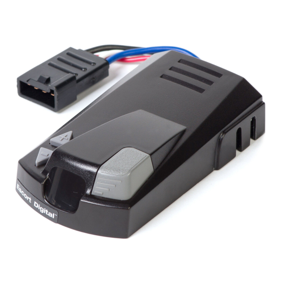
DIGITAL
®
Electronic Brake Control
IMPORTANT:
Read the following instructions carefully before
installing and/or operating the brake control. If
you have any concerns with this product or
the installation process, our technical support
team can assist you. Call (877) 544 4449.
A
D
C
B
A. Vertical slide button for manual override
B. Digital display
C. Digital power setting buttons
D. Mounting bracket holes
INSTALLATION PRECAUTIONS:
Braking capacity is for 2, 4 or 6 trailer brake applications.
l
This brake control will apply the trailer brakes while in
l
reverse.
This brake control is not reverse polarity protected. Reversing
l
the connection to the vehicle battery or the breakaway battery
on the trailer will damage the brake control.
This brake control is designed to operate with electric trailer
l
brakes and electric-hydraulic brake systems.
WIRING GUIDE:
The ESCORT
®
DIGITAL
™
came equipped with a quick connector
plug wired to the back of the controller.
OPTION: If your vehicle came equipped with a factory tow
package, brake control function wires may exist under the
vehicle dash (usually found under the driver side dash). Consult
vehicle manual or call for location. Purchase a vehicle specific
Plug-in Simple!
brake control quick connector and simply plug
®
into the factory tow package plug.
Plug-In Simple
®
Connector Instructions
1. Plug the Husky
®
Plug-In Simple!
connector into the vehicle
®
connector located under dash.
2. Test all functions.
UNIVERSAL INSTALLATION
Remove the quick connector plug on the brake control and
splice the wires to the function wires.
QUICK INSTALL OPTION
See store personnel to purchase Plug-In Simple!
control connector
LIMITED LIFETIME WARRANTY
Hopkins Manufacturing Corporation warrants
®
®
®
™
Quest
, Escort
and Escort
Digital
brake
control products to be free from defects in
material and workmanship, under normal use and
service, for the original buyer's lifetime from the
date of original purchase.
This warranty does not cover, and Hopkins
Manufacturing Corporation is not liable for, the
cost of repair or replacement of parts which
have been subjected to misuse, negligence,
accident, improper installation, modification, or
normal deterioration due to wear and exposure,
or defects caused by unauthorized repairs. THE
ORIGINAL BUYER'S EXCLUSIVE REMEDIES UNDER
THIS LIMITED WARRANTY SHALL BE LIMITED TO
REPAIR OR REPLACEMENT (AT THE OPTION OF
HOPKINS MANUFACTURING CORPORATION) OF
THE DEFECTIVE PRODUCT OR PART. The repair
or replacement of the product or part under
warranty will be made by Hopkins Manufacturing
Corporation without charge for parts or labor.
UNDER NO CIRCUMSTANCES WILL HOPKINS
MANUFACTURING CORPORATION BE LIABLE FOR
INCIDENTAL OR CONSEQUENTIAL DAMAGES,
INCLUDING BUT NOT LIMITED TO DAMAGE TO
OR LOSS OF OTHER PROPERTY OR EQUIPMENT.
Some states do not allow the exclusion or
limitation of incidental or consequential damages,
so the above limitations or exclusions may not
apply to you. This warranty gives you specific
legal rights, and you may also have other rights
which vary from state to state.
In order to obtain performance under this
warranty, return the defective product, postage
prepaid, along with dated proof of purchase, to
Hopkins Manufacturing Corporation, 428 Peyton,
Emporia, Kansas 66801-1157. This warranty does
not cover shipping and delivery charges to or from
Hopkins Manufacturing Corporation.
311-0288-176 Rev H 2/13
© 2010 Hopkins Manufacturing Corporation
™
White wire – ground/negative terminal (-) on battery
Blue wire – trailer electric brakes
Black wire – positive terminal (+) on battery
Red wire – cold side of stop lamp switch or brake light
CAUTION: Wire colors vary by manufacturer. Be sure to wire by
function only.
VEHICLE MANUFACTURER WIRING CODES:
BRAKE
CONTROL WIRE
BLUE
BLACK
______________________________________________________________
____
FORD 94-07
BLUE
RED
______________________________________________________________
____
CHEV/GM 99-06
DK BLUE
RED
______________________________________________________________
____
CHEV/GM 07-08
DK BLUE
RED w/BLK
______________________________________________________________
____
DODGE 97-02
BLUE
RED
______________________________________________________________
____
DODGE 03-07
BLUE
WHITE w/RED
______________________________________________________________
____
NISSAN
BRN w/WHT RED
______________________________________________________________
____
TOYOTA
RED
BLACK w/RED
1. Be sure to use proper wire gauge when installing your
control (12 gauge for electric brakes, power and ground / 16
gauge for the stoplight switch).
2. Connect white wire to negative post on the vehicle battery.
Grounding to any other location may cause intermittent
brake control operation or failure.
3. Attach 30 amp circuit breaker or in-line fuse to the positive
terminal on the vehicle's battery. Route black wire from the
brake control to the fuse or breaker.
4. Splice red wire into cold side of vehicle's stoplight switch
located by the brake pedal. Find the wire by using a circuit
tester and probing for the wire that powers the vehicle
stoplights when the brake pedal is pressed.
5. Route blue wire from brake control to vehicle side trailer
connector.
6. Plug harness into the plug wired to the back of the controller.
IMPORTANT: Please see "vehicle specific
instructions" and "special notes" before every installation.
IMPORTANT INSTALLATION TIPS
Wire color codes vary by manufacturer. Be sure to wire by
l
function only.
Some late model Ford / Mercury trucks and sport utility
l
vehicles have two or more stoplight switch wires. For proper
operation, use the light green wire. The other wire is red with
a green stripe. This wire goes directly to ground when not in
use. Splicing into this wire will short circuit your brake control
and possibly destroy the unit.
VEHICLE SPECIFIC INSTRUCTIONS
YEAR
MAKE
1989 – 91
Ford
1992 – 93
Ford
1992 – 93
Ford
1994 – 99
Ford
1997 – 02
Ford
1988 – 93
GM
1994
GM
1995 – 96
GM
1988 – 93
Chrysler
1994 – 95
Chrysler
1996 – 02
Chrysler
1988 – 90
Jeep
brake
®
1991 – 93
Jeep
1994 – Present
Jeep
GARANTIE LIMITÉE À VIE
Hopkins Manufacturing Corporation garantit
à l'acheteur original que, à partir de la date
d'achat, pour un usage normal, chaque produit de
®
commande de frein Quest
, Escort
Digital
™
sera exempt de défaut de matière
première ou de fabrication.
Cette garantie ne couvre pas les coûts de
réparation ou de remplacement de pièces
attribuables à une utilisation inappropriée,
un accident, une installation incorrecte, une
modification, ou une détérioration normale
causée par l'usure ou des défectuosités
dues à des réparations non approuvées.
Hopkins Manufacturing Corporation ne sera
pas responsable des dommages énumérés ci
haut. PAR LA PRÉSENTE GARANTIE LIMITÉE,
LE SEUL RECOURS EXCLUSIF DE L'ACHETEUR
ORIGINAL SE LIMITE AUX RÉPARATIONS ET
REMPLACEMENTS (AU CHOIX DE HOPKINS
MANUFACTURING CORPORATION) DES PRODUITS
OU PIÈCES DÉFECTUEUSES. Les réparations ou
remplacements de produits et pièces couvertes
par la garantie seront effectuées par Hopkins
Manufacturing Corporation sans frais de pièces ou
de main-d'œuvre.
EN AUCUNE CIRCONSTANCE HOPKINS
MANUFACTURING CORPORATION NE SERA
RESPONSABLE DE DOMMAGES ACCESSOIRES OU
INDIRECTS, Y COMPRIS MAIS SANS LIMITATAION,
LES DOMMAGES, LES PERTES MATÉRIELLES
OU LES PERTES D'ÉQUIPEMENT. Certains états
n'autorisent pas l'exclusion ou la limitation
de responsabilité relatives aux dommages
accessoires ou indirects. Il est donc possible
que les exclusions ou limitation ci-dessus ne
s'appliquent pas dans votre cas. La présente
garantie vous donne des droits juridiques
spécifiques et vous pouvez également disposer
d'autres droits qui varient selon les états.
Pour obtenir l'exécution de cette garantie, veuillez
retourner le produit défectueux, avec une preuve
d'achat, affranchissement pré-payé, à Hopkins
Manufacturing Corporation, 428 Peyton, Emporia,
Kansas 66801-1157. La présente garantie ne
couvre pas les frais de livraison et d'expédition
à destination ou en provenance de Hopkins
Manufacturing Corporation.
For Chevrolet vehicles 1999 and up : If your vehicle does
l
not have the towing package, only the ground and stoplight
switch will be active in the Plug-In Simple
electric brake wire and 12-volt power lead will be terminated
outside the firewall. These will have to be routed to the trailer
connector and battery on the vehicle.
Be sure your brake control is grounded properly. The ground
l
wire should be connected to the negative post on the battery.
Grounding in any other location may cause the control to
RED
WHITE
operate intermittently.
GREEN
WHITE
Ford and Dodge tow packages come with a 20 amp battery
l
feed wire system which will accommodate 2 and 4 brake
LT BLUE
BLACK
magnets. An upgrade to a 30 amp (12 gauge) battery wire
LT BLUE w/WHT WHITE
system will be needed for 6 and 8 braking systems.
WHITE
BLACK
MOUNTING YOUR
BLUE w/WHT
GRN w/BLK
BRAKE CONTROL
1. Your Husky
®
RED w/GRN
BLACK
brake control can
GRN w/ WHT
BROWN
be mounted in any
direction, including
upside down.
2. Mount the bracket to a secure location with Phillips screws
provided (E) where you will be able to view the display
and easily access the vertical slide.
3. Once you have chosen a location, check behind the dash to be
sure there are no damageable components in the chosen
location. Using the bracket as a template, drill holes in the
dash.
4. Attach bracket with 2 provided screws and attach control to
bracket (F) with 2 remaining screws.
5. Plug wiring to controller.
CAUTION: Using large/longer screws may damaga the unit.
OPERATING AND SETTING
YOUR CONTROL
1. Once installed, your control will show "." on the digital
display when trailer is connected. Once your
trailer is connected, power will be shown in increments of
5%
TROUBLE SHOOTING GUIDE
CONDITION
"." [dot]
"SC" [flashing]
No power to trailer
Trailer brakes on all the time
VEHICLE STOP LIGHT SWITCH WIRE
COLOR
MODEL
E & F-Series
Light Green
F-Series
Light Green
E-Series
Light Green with Red Stripe
E & F-Series
Light Green
Expedition & Navigator
Light Green
Pickups
White
Pickups
Yellow
Pickups & SUV's
White
Pickups
White
Pickups
White with Brown Stripe
Pickups & SUV's
White with Brown Stripe
All
Light Blue with Black Stripe
All
White with Brown Stripe
All
CONTACT YOUR JEEP DEALER.
GARANTÍA LIMITADA
Hopkins Manufacturing Corporation garantiza que
los productos de control de freno Quest
e Escort
®
Digital
®
®
et Escort
sus materiales ni en su fabricación, siempre que
se utilicen normalmente y se realice el debido
mantenimiento, mientras lo utilice el comprador
original y a partir de la fecha de la compra
original.
Esta garantía no cubre, ni Hopkins Manufacturing
Corporation se responsabiliza por, el costo
de reparación o reemplazo de piezas que
hayan sido utilizadas de modo incorrecto,
sujetas a negligencias o accidentes, instaladas
inadecuadamente, modificadas o deterioradas
por desgaste normal y exposición o con defectos
producidos por reparaciones no autorizadas.
LAS SOLUCIONES ADOPTADAS POR EL
COMPRADOR ORIGINAL SEGÚN LA PRESENTE
GARANTÍA ESTARÁ LIMITADA A REPARACIONES
O REEMPLAZOS (A DISCRECIÓN DE HOPKINS
MANUFACTURING CORPORATION) DEL PRODUCTO
O LA PIEZA QUE PRESENTE DEFECTOS. La
reparación o el reemplazo del producto o la pieza
que cubre la garantía y el costo de las piezas,
o la mano de obra estarán a cargo de Hopkins
Manufacturing Corporation,
BAJO NINGÚN CONCEPTO HOPKINS
MANUFACTURING CORPORATION SE
RESPONSABILIZARÁ POR DA—OS ACCIDENTALES
O RESULTANTES, LO QUE INCLUYE ENTRE OTROS,
DA—OS O PÉRDIDAS DE OTRAS PROPIEDADES
O EQUIPOS. Algunos estados no permiten la
exclusión o limitación de daños accidentales
o resultantes, de modo que las limitaciones o
exclusiones presentadas arriba posiblemente no
correspondan a su caso. Esta garantía le otorga
derechos legales específicos y es posible que
cuente con otros derechos que pueden variar de
un estado a otro.
Para obtener los beneficios de esta garantía,
devuelva el producto defectuoso vía postal,
con franqueo pagado, junto con una prueba
de compra con fecha a Hopkins Manufacturing
Corporation, 428 Peyton, Emporia, Kansas 66801-
1157. Esta garantía no cubre los costos de envío
y entrega a y desde Hopkins Manufacturing
Corporation.
on the display. Five represents the lowest power, 99 the
highest.
®
connector. The
2. The (+) and (-) buttons adjust power sent to the trailer.
Pressing the brake pedal and pressing the (+) and (-) buttons
changes the intensity of power.
3. Connect your trailer and test drive in an open area to set the
level of power.
4. Drive forward at approximately 20 miles per hour and apply
the brakes. If brakes appear too weak, press the (+) button
for additional power. If brakes lock up, press the (-) button to
reduce power. Continue this step until smooth braking is
reached.
IMPORTANT NOTES ABOUT YOUR HOPKINS®
BRAKE CONTROL
E
Brake lights on the vehicle and trailer activate when the
l
manual slide button is pushed.
Unit is short-proof protected from electric trailer brake and
l
brake light wiring shorts.
Brake control adjustments may need to be made for different
F
l
road conditions and trailer loads.
Always test your brake power levels at low speed before every
l
trip. Weather conditions and varying trailer loads may require
adjustments to the brake control power.
Limited lifetime warranty.
l
Product Information: salesinfo@huskytow.com
PROBABLE CAUSE
Trailer is connected
Trailer electric brake wire (blue) short or defective magnet
Check vehicle and trailer connector pin outs
Check vehicle and trailer connector pin outs
WIRE LOCATION
Located in C-shaped connector on steering column; 2nd pin on the top row of 7.
4-pin connector in center of vehicle under dash.
4-pin connector next to brake pedal.
Under dash to the right of the steering column.
Under dash to the right of the steering column.
Under dash near top of brake pedal.
Under dash near top of brake pedal.
Connector on left of steering column. There are several white wires in this connector.
The correct wire is located in position "F".
Under dash near top of brake pedal.
Under dash near top of brake pedal.
Under dash to the left of the steering column.
Under dash near top of brake pedal.
Under dash near top of brake pedal.
®
®
, Escort
™
no presentan defectos en
Questions? Contact us at:
Tech Support: techinfo@huskytow.com
Sales Phone: (800) 495 5858
Tech Support Phone: (877) 544 4449
www.huskytow.com
Advertisement
Table of Contents

Related Manuals for Husky ESCORT DIGITAL


Summary of Contents for Husky ESCORT DIGITAL
- Page 1 Plug-In Simple ® Connector Instructions 1992 – 93 Ford E-Series Light Green with Red Stripe 4-pin connector next to brake pedal. 1. Plug the Husky ® Plug-In Simple! connector into the vehicle ® 1994 – 99 Ford E & F-Series Light Green Under dash to the right of the steering column.
- Page 2 MARRÓN MONTANDO SU CONTROL DE FRENO remolque. 1. Asegúrese de usar los cables del calibre apropiados cuando 1. Su control de freno Husky puede ser montado en cualquier ® Siempre compruebe los niveles de energía de sus frenos a esté instalando su control (calibre 12 para frenos electrónicos, dirección, incluyendo hacia arriba o abajo.
Need help?
Do you have a question about the ESCORT DIGITAL and is the answer not in the manual?
Questions and answers