
Related Manuals for BRUEL & KJAER 2245


Summary of Contents for BRUEL & KJAER 2245
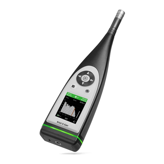
- Page 1 Sound Level Meter Type 2245 with Microphone Type 4966 From Hardware Version 1.0 Instruction Manual...
-
Page 2: Table Of Contents
Instruction Manual Sound Level Meter Types 2245 – Page 2 of 110 Contents Table of Contents Chapter 1 Introduction ................... 5 About This Manual ..................5 1.1.1 Conventions Used in this Manual ............ 5 System Overview ..................5 1.2.1 Hardware and Software on the Sound Level Meter ......5 1.2.2... - Page 3 Instruction Manual Sound Level Meter Types 2245 – Page 3 of 110 Wi-Fi and Bluetooth during tests.............. 37 Mounting for Acoustical Tests ..............37 Periodic Testing of Acoustical Frequency Responses ......38 Mounting for Mechanical Vibrations Tests ..........38 Testing 1/1-octave-band and 1/3-octave-band Filters ......38 EMC Test Procedures ................
- Page 4 Instruction Manual Sound Level Meter Types 2245 – Page 4 of 110 4.13 Wireless interface to the Sound Level Meter ........... 65 4.13.1 Bluetooth..................65 4.13.2 Wi-Fi ....................65 4.14 Electrical interface to the Sound Level Meter .......... 65 4.14.1 Output for Headphone and test .............
-
Page 5: Chapter 1 Introduction
Introduction About This Manual This Instruction Manual for Sound Level Meter Type 2245 has been created to fulfil the documentation requirements of the national and international standards that the sound level meter conform to. These standards are listed in section 4.2. -
Page 6: Hardware Setup
This section provides an overview of the hardware components used with the sound level meter. A hardware overview is provided in Fig. 1.1, optional accessories are designated on the diagram. The components needed for conformance testing Sound Level Meter Type 2245 are listed in Table 1.1. Fig. 1.1 Hardware overview... - Page 7 AO-0821-D-010 USB Shielded I/O Cable, Type A-to-C, USB 2.0, 1.0m, for Sound Level Meter Type 2245 AO-0846 USB-C to 3.5mm (Mini) Jack Adapter for analog Headphone, for Sound Level Meter Type 2245 HT-0015 Earphones, unscreened cable Type 4231 Sound Calibrator...
-
Page 8: Block Diagrams
Instruction Manual Sound Level Meter Types 2245 – Page 8 of 110 1.2.4 Block Diagrams The Block Diagram for Sound Level Meter Type 2245 is shown in Fig. 1.2. Fig. 1.2 Block Diagram for Type 2245 Output Amplifier Converter WiFi... -
Page 9: Chapter 2 Short Guide To The Sound Level Meter
Instruction Manual Sound Level Meter Types 2245 – Page 9 of 110 Chapter 2 Short Guide to the Sound Level Meter Introduction This chapter contains a brief guide to the use of the sound level meter. The user interface of the sound level meter is classic: A screen for displaying settings, results and status ... -
Page 10: Measurement Settings
Instruction Manual Sound Level Meter Types 2245 – Page 10 of 110 2.3.1 Measurement settings The acoustical frequency response and calibration depends on the sound field, the microphone, the microphone accessories used and the electrical frequency response. To improve the quality of the measurement and help the user to measure correctly the... - Page 11 Instruction Manual Sound Level Meter Types 2245 – Page 11 of 110 Use Measurement settings > Measurement control to setup how to control your measurement: Enabled Logging mode: Select to log measurement data at every Logging interval. Preset Measurement time: Select...
- Page 12 Instruction Manual Sound Level Meter Types 2245 – Page 12 of 110 Use Measurement settings > Spectrum parameters to select Bandwidth (1/1- octave or 1/3-octave ), Frequency Weighting to use and the spectrum parameters to measure. The use of keyboard in this display.
-
Page 13: Display Settings
Instruction Manual Sound Level Meter Types 2245 – Page 13 of 110 2.3.2 Display settings Use Display settings > Screen brightness and > Light ring brightness to adjust the brightness of the screen and light ring on the instrument. Light Dark Use Display settings >... -
Page 14: Calibration History
Instruction Manual Sound Level Meter Types 2245 – Page 14 of 110 2.3.5 Calibration history ???? 2.3.6 Status Use Status to see the Battery and Disk status: The small icon in the bottom left corner of the display gives a brief overview of the battery status. -
Page 15: Calibration
Instruction Manual Sound Level Meter Types 2245 – Page 15 of 110 Calibration Calibration is an adjustment of your sound level meter to measure and display correct values. The sensitivity of the microphone as well as the response of the electronic circuitry can vary slightly over time or could be affected by environmental conditions such as temperature and humidity. - Page 16 Instruction Manual Sound Level Meter Types 2245 – Page 16 of 110 4. Use right arrow button to enter Calibration and insert the Calibrator serial no. (use up/down arrow buttons to change the number) 5. Use right arrow button to enter Calibrate: 6.
-
Page 17: Calibration Check Procedure
Instruction Manual Sound Level Meter Types 2245 – Page 17 of 110 10. Press the button to accept the calibration and remove the calibrator. It will automatically switch off after a few seconds. If no calibration signal is detected, you will be informed about an unstable calibration signal and asked to mount the calibrator, switch it on and press Retry to restart the calibration. - Page 18 Instruction Manual Sound Level Meter Types 2245 – Page 18 of 110 6. The sound level meter will detect the signal and pop up the message: 7. Press the button to start the calibration check Detection signal appears on the screen as feedback. When the signal has...
-
Page 19: Measuring With The Sound Level Meter
Instruction Manual Sound Level Meter Types 2245 – Page 19 of 110 Note: You can disable the automatic calibration check in System settings > Advanced settings > Calibration: Measuring with the sound level meter Before a measurement is started and after it is stopped, the sound level meter displays an instantaneous broadband measurement. -
Page 20: Overload And Underrange
Instruction Manual Sound Level Meter Types 2245 – Page 20 of 110 Press again to reset the measurement and display, ready for a new measurement. 2.5.2 Overload and Underrange ???? Looking at the measurement There is a number of measurement displays (SLM, List, Spectrum, Profile and About... -
Page 21: Looking At Saved Measurements
Instruction Manual Sound Level Meter Types 2245 – Page 21 of 110 Looking at saved measurements Open a saved measurement by pressing and then selecting it in Data explorer:... - Page 22 Instruction Manual Sound Level Meter Types 2245 – Page 22 of 110 5.1.6 ..The Instruction Manual shall describe appropriate procedures for use of the sound level meter. 5.18.5 When results of a measurement are provided at a digital output, the Instruction Manual shall describe the method for transferring or downloading of digital data to an external data-storage or display device.
-
Page 23: Placing The Microphone (Sound Level Meter)
Instruction Manual Sound Level Meter Types 2245 – Page 23 of 110 Placing the Microphone (Sound Level Meter) The sound level meter must be placed away from shielding, reflecting, or absorbing objects. In a diffuse sound field, absorbing objects will reduce the measured sound levels. -
Page 24: Measuring At Low Static Pressure
Instruction Manual Sound Level Meter Types 2245 – Page 24 of 110 Fig. 2.1 Error from self-generated noise Fig. 2.1 shows the error on the measured sound levels from the presence of self- generated noise. The curve can also be used for compensation by subtracting the error from the measured sound levels. -
Page 25: Mechanical Vibration
Instruction Manual Sound Level Meter Types 2245 – Page 25 of 110 Fig. 2.3 Typical variation in sensitivity at 250 Hz from that at 101.3 kPa as a function of ambient pressure At the Calibration Check Frequency (1 kHz), the recommended Brüel & Kjær Sound Calibrator Type 4231 is rather insensitive to variations in the static pressure –... - Page 26 Instruction Manual Sound Level Meter Types 2245 – Page 26 of 110 Table 2.1 Frequency weighting design goals Exact Frequency Weightings Nominal Frequency (1 decimal) Frequency (6 digits) (dB) (Hz) (Hz) 10.0000 -70.4 -38.2 -14.3 12.5893 -63.4 -33.2 -11.2 15.8489 -56.7...
-
Page 27: Measured Quantities
Instruction Manual Sound Level Meter Types 2245 – Page 27 of 110 2.14 Measured Quantities This section gives a precise mathematical definition of the measured quantities and defines the abbreviations used on the display. 2.14.1 Instantaneous Broadband Measurements These measurements are done continuously, independent of measurement Start, Pause and Stop. - Page 28 Instruction Manual Sound Level Meter Types 2245 – Page 28 of 110 Table 2.2 Exponential time constants and corresponding averaging times Time Weighting Time Constant Averaging (seconds) Time (seconds) Fast 0.125 0.25 Slow Time-weighted Sound Level, I Time-weighted The I (Impulse) time-weighted sound level,...
-
Page 29: Timed Broadband Measurements
Instruction Manual Sound Level Meter Types 2245 – Page 29 of 110 Sound Pressure Level (SPL) (SPL)(T The sound pressure level, , is defined as the greatest time-weighted sound level, , within a time interval starting at and ending at Δ... - Page 30 Instruction Manual Sound Level Meter Types 2245 – Page 30 of 110 Press Stop to a stopped measurement to reset the latched overload and to reset all time-weighted sound levels to zero (–∞ dB). From this, they increase to their current values.
- Page 31 Instruction Manual Sound Level Meter Types 2245 – Page 31 of 110 Equivalent Continuous Sound Level The equivalent continuous sound level (also called time-average sound level), , is defined as twenty times the logarithm to base ten of the ratio of a root-mean-square sound pressure during a time interval to the reference sound pressure, sound pressure being obtained with a frequency weighting, x.
- Page 32 Instruction Manual Sound Level Meter Types 2245 – Page 32 of 110 Taktmaximal-Mittelungspegel The Taktmaximal-Mittelungspegel, , is defined as ten times the logarithm to AFTeq (Tn) base ten of the mean of ten to the power of the Taktmaximalpegel, , divided by ten during a time interval.
- Page 33 Instruction Manual Sound Level Meter Types 2245 – Page 33 of 110 Peak Sound Level The peak sound level, , is defined as twenty times the logarithm to base ten of xpeak the ratio of the greatest absolute instantaneous sound pressure,...
-
Page 34: Spectrum Measurements
Instruction Manual Sound Level Meter Types 2245 – Page 34 of 110 2.14.3 Spectrum Measurements The definition of the measured quantities is the same as for the broadband measurements. At low frequency bands the exponential time constants for Fast and Slow weighting are modified to get a reasonable B*T product, see section 4.11.5. -
Page 35: Overload And Underrange
Instruction Manual Sound Level Meter Types 2245 – Page 35 of 110 2.15 Overload and Underrange 2.15.1 Overload Overload indicates that the input signal level exceed the capability of the sound level meter with the current settings. During measurement, overload is indicated with the flashing red triangle and by a flashing red “traffic light”... -
Page 36: Chapter 3 Conformance Testing
Instruction Manual Sound Level Meter Types 2245 – Page 36 of 110 Chapter 3 Conformance Testing Introduction This chapter contains the information needed to conduct conformance testing according to the specified standards. Microphone, Accessories and Sound Fields The acoustical frequency response and calibration depends on the sound field, the microphone, the microphone accessories used and the electrical frequency response. -
Page 37: Electrical Substitute For Microphones
Instruction Manual Sound Level Meter Types 2245 – Page 37 of 110 For acoustic calibration the Brüel & Kjær Sound Level Calibrator Type 4231 shall be used and selected in System settings >Advanced settings > Calibration > Calibrator. The adjustment data according to IEC 61672-1 paragraph 5.2.4 for Microphone Type 4966 with Sound Calibrator Type 4231 is 93.85 dB for the 94 dB setting of the calibrator. -
Page 38: Periodic Testing Of Acoustical Frequency Responses
Instruction Manual Sound Level Meter Types 2245 – Page 38 of 110 The sound level meter can be mounted using Tripod Extension for Hand-held Analyzers UA-1651. The tripod extension stem is screwed into the Tripod Mounting Thread situated on the rear end of the sound level meter. The thread on the other end of the stem is used to mount the assembly to the test rig. -
Page 39: Reference Orientation
Instruction Manual Sound Level Meter Types 2245 – Page 39 of 110 Fig. 3.1 Setting up the signal source for an immunity test To prevent the acoustic source from being affected by acoustic noise in the surroundings, the following method can be used. -
Page 40: Accessories Included In Emc Test
The following accessories are connected to the instrument during the EMC tests: Mains Power Supply ZG-xxxx is connected to the 'USB' socket on the rear pannel of 2245 using a USB cable AO-xxxx. Detailed descriptions of the parts are given in Table 1.1. 3.9.5... - Page 41 Instruction Manual Sound Level Meter Types 2245 – Page 41 of 110 Only 1/3-octave-band filters need to be tested. This is because the filters are digital, and no disturbance at the filter input will show up to be greater at 1/1-octave...
-
Page 42: Chapter 4 Specifications
Environmental Conditions, and with the sound level meter calibrated to the nominal microphone open circuit sensitivity. Standards The sound level meter part of the Sound Level Meter Type 2245 conforms to the following national and international standards and classes/types/groups with the accessories and configurations specified in section 1.2.3: IEC 61672–... -
Page 43: Reference Conditions For Acoustic Calibration
Instruction Manual Sound Level Meter Types 2245 – Page 43 of 110 Reference Conditions for Acoustic Calibration Reference Level Range: Only one level range exists and this is the reference level range. Reference Sound Pressure Level: 94.00 dB re. 20 μPa... -
Page 44: Frequency Responses
Instruction Manual Sound Level Meter Types 2245 – Page 44 of 110 Frequency Responses The frequency responses are given in tabular form in Appendix A and in graphical form in this section. The specifications for the Lin response defined in IEC 60651 are equivalent to those given here for the Z-weighting. -
Page 45: Typical Low-Frequency Responses
Instruction Manual Sound Level Meter Types 2245 – Page 45 of 110 Fig. 4.1 Uncompensated electrical frequency response, corresponds to Table 4.6.2 Typical Low-frequency Responses The typical Low-frequency Responses for Z frequency weighting are given in Fig. 4.2. The electrical responses in Fig. 4.2. is the Low-frequency Responses for introduction of the electrical signal through the recommended means to substitute the microphone with an electrical input facility (see section 3.3.2) -
Page 46: Acoustical Frequency Responses
Instruction Manual Sound Level Meter Types 2245 – Page 46 of 110 4.6.3 Acoustical Frequency Responses All the acoustical frequency responses are given for Z frequency weighting. The A-, B- and C-weighted acoustical frequency responses can be found by adding the appropriate response from the “Add to Acoustical Responses”... -
Page 47: Free-Field Frequency Responses For Diffuse-Field Calibrated Instruments
Instruction Manual Sound Level Meter Types 2245 – Page 47 of 110 Fig. 4.5 Diffuse-field frequency response for the sound level meter. Corresponds to the “Acoustical Response” column in Table A. 4. Fig. 4.6 Diffuse-field frequency response for the sound level meter with Windscreen UA-1650. -
Page 48: Directional Responses
Instruction Manual Sound Level Meter Types 2245 – Page 48 of 110 Directional Responses This section gives directional responses for plane progressive sinusoidal sound waves normalised to the response in the reference direction. Influence of the windscreen UA- 1650 is also given as tables in Appendix A. Only the resulting directional responses are given here as graphs. - Page 49 Instruction Manual Sound Level Meter Types 2245 – Page 49 of 110 Fig. 4.7 Directional response for the sound level meter, measured in a plane parallel to the display and along the microphone axis. Corresponds to Table A.7 to Table A.9...
- Page 50 Instruction Manual Sound Level Meter Types 2245 – Page 50 of 110 Fig. 4.8 Directional response for the sound level meter, measured in a plane perpendicular to the display and along the microphone axis. Corresponds to Table A.10 to Table A.12...
- Page 51 Instruction Manual Sound Level Meter Types 2245 – Page 51 of 110 Fig. 4.9 Sensitivity variations of the sound level meter, at sound incidence angles within ±Ɵ ° from the reference direction. Corresponds to Table A.13...
- Page 52 Instruction Manual Sound Level Meter Types 2245 – Page 52 of 110 Fig. 4.10 Directional response for the sound level meter with Windscreen UA- 1650, measured in a plane parallel to the display and along the microphone axis. Corresponds to Table A.17 to Table A.19...
- Page 53 Instruction Manual Sound Level Meter Types 2245 – Page 53 of 110 Fig. 4.11 Directional response for the sound level meter with Windscreen UA- 1650, measured in a plane perpendicular to the display and along the microphone axis. Corresponds to Table A.20 to Table A.22...
- Page 54 Instruction Manual Sound Level Meter Types 2245 – Page 54 of 110 Fig. 4.12 Sensitivity variations of the sound level meter with Windscreen UA- 1650, at sound incidence angles within ±Ɵ ° from the reference direction. Corresponds to Table A.23...
-
Page 55: Self-Generated Noise
Instruction Manual Sound Level Meter Types 2245 – Page 55 of 110 Self-generated Noise Self-generated noise is given for nominal microphone Open Circuit Sensitivity, with Free-field Measurement settings > Input > Sound Field set to and no microphone accessories selected. -
Page 56: Measuring Ranges
Instruction Manual Sound Level Meter Types 2245 – Page 56 of 110 Fig. 4.14 Typical self-generated noise, 1/3 octave band Measuring Ranges The Upper Limit in the following sections is based on the guaranteed worst-case limit for the sound level meter and the nominal Open Circuit Sensitivity of the microphone. -
Page 57: Primary Indicator Range
Instruction Manual Sound Level Meter Types 2245 – Page 57 of 110 4.9.3 Primary Indicator Range Primary Indicator Range according to the International Standard IEC 60651: Table 4.4 Primary Indicator Range Lower Limit Upper Limit A-weighting B-weighting C-weighting Z-weighting (dB) -
Page 58: Pulse Range
Instruction Manual Sound Level Meter Types 2245 – Page 58 of 110 4.9.6 Pulse Range Pulse Range according to the international standard IEC 60804 is the difference between the Upper and Lower Limit in the following table: Table 4.7 Pulse Range... -
Page 59: Detectors
Instruction Manual Sound Level Meter Types 2245 – Page 59 of 110 4.10 Detectors broadband bars and spectra every 0.2 s; all other spectra Display-update Rates: and numbers every 1 s. 4.10.1 Exponential Averaging Exponential Averaging Times: Fast (250 ms), Slow (2000 ms), Impulse (70 ms + 1500 ms hold time. -
Page 60: Linear Averaging
Instruction Manual Sound Level Meter Types 2245 – Page 60 of 110 4.10.2 Linear Averaging Linear Averaging Times: 1 second to 24 hours, in steps of 1 second Settling Time According to IEC 60804: <2 seconds Nominal Delay Time between operation of the reset facility and re-initiation of a measurement according to IEC 61672–1: <3 seconds... -
Page 61: 1/3-Octave Band Centre Frequencies
Instruction Manual Sound Level Meter Types 2245 – Page 61 of 110 Fig. 4.16 The shapes of the 1/1-octave band filters (from 0 to –3.5 dB). The innermost and outermost curves show IEC 61260 limits 4.11.2 1/3-octave Band Centre Frequencies Nominal: 12.5 Hz, 16 Hz, 20 Hz, 25 Hz, 31.5 Hz, 40 Hz, 50 Hz, 63 Hz, 80 Hz, 100 Hz, 125... - Page 62 Instruction Manual Sound Level Meter Types 2245 – Page 62 of 110 Fig. 4.18 The shapes of the 1/3- octave band filters (from 0 to –3.5 dB). The innermost and outermost curves show IEC 61260 limits...
-
Page 63: Linear Operating Range
Instruction Manual Sound Level Meter Types 2245 – Page 63 of 110 4.11.3 Linear Operating Range Linear Operating Range according to the international standard IEC 61260, for electrical input, for all filters in the filter banks: Table 4.11 Linear Operating Range... -
Page 64: Influence From The Operating Environment
Instruction Manual Sound Level Meter Types 2245 – Page 64 of 110 For a white Gaussian signal and for 1/1-octave centre frequencies from 16 Hz to 63 Hz, these time constants give a maximum relative standard deviation of approximately 1.5 dB. -
Page 65: Immunity To Power And Radio-Frequency Fields
Instruction Manual Sound Level Meter Types 2245 – Page 65 of 110 4.12.6 Immunity to Power and Radio-frequency Fields Fig. 4.19 The most sensitive direction 4.13 Wireless interface to the Sound Level Meter It is not possible to change or corrupt the measured values in any way through these interfaces. -
Page 66: Digital Interfaces
Instruction Manual Sound Level Meter Types 2245 – Page 66 of 110 Information on the signal source, frequency weighting and gain Maximum Peak Output Voltage: ±4.46 V Maximum Sinusoidal Output Voltage: 3.16 V Output Impedance: 50 Ω Load Impedance: >15 kΩ÷çç< 1 nF for <0.2 dB attenuation from DC to 20 kHz, short- circuit proof without affecting the measurement results Max DC Offset: ±15 mV... -
Page 67: Warm-Up Time
Instruction Manual Sound Level Meter Types 2245 – Page 67 of 110 Charge Time: In instrument, typically 10 hours from empty at ambient temperatures below 30 °C. To protect the battery, charging will be terminated completely at ambient temperatures above 40 °C. At 30 to 40 °C charging time will be prolonged. With external charger ZG-0444 (optional accessory), typically 5 hours. -
Page 68: Chapter 5 Regulatory
Instruction Manual Sound Level Meter Types 2245 – Page 68 of 110 Humidity IEC 60068–2–78: Damp Heat: 93% RH (non-condensing at +40 °C (104 °F)). Recovery time 2 ??4 hours Mechanical Non-operating: IEC 60068–2–6: Vibration: 0.3 mm, 20 m/s2, 10 – 500 Hz IEC 60068–2–27: Bump: 1000 bumps at 400 m/s2... -
Page 69: Ic (Industry Canada Statement)
Instruction Manual Sound Level Meter Types 2245 – Page 69 of 110 to radio communications. However, there is no guarantee that interference will not occur in a particular installation. If this equipment does cause harmful interference to radio or television reception, which can be determined by turning the equipment off... -
Page 70: Appendix A Tables
Instruction Manual Sound Level Meter Types 2245 – Page 70 of 110 Appendix A Tables Electrical Frequency Responses Uncompensated electrical frequency responses for the different frequency weightings. Please see the instructions in section 3.2.2 on how to ensure an uncompensated electrical frequency response. - Page 71 Instruction Manual Sound Level Meter Types 2245 – Page 71 of 110 Exact Electrical Add to Acoustical Nominal Frequency Frequency (6 digits) (Hz) weighting weighting weighting weighting weighting weighting weighting (Hz) 3000 2985.38 1.19 -0.39 -0.49 0.01 1.19 -0.39 -0.48 3162.28...
-
Page 72: Free-Field Frequency Responses
Instruction Manual Sound Level Meter Types 2245 – Page 72 of 110 Free-field Frequency Responses Frequency responses with Z frequency weighting. Measured with plane progressive sinusoidal sound waves incident from the reference direction and the sound level meter’s Sound field set to Free-field , see section 4.6. - Page 73 Instruction Manual Sound Level Meter Types 2245 – Page 73 of 110 Nominal Exact Microphone Expanded Body Expanded Electrical Acoustical Expanded Frequency Frequency Free-field Uncertainty Influence Uncertainty Response Response Uncertainty (6 digits) Response 3750 3758.37 -0.11 0.12 0.08 0.15 0.14 0.11...
- Page 74 Instruction Manual Sound Level Meter Types 2245 – Page 74 of 110 Table A. 3 Free-field 0° frequency response for the sound level meter with Windscreen UA-1650 Nominal Exact Microphone Expanded Body Expanded Influence Expanded Electrical Acoustical Expanded Frequency Frequency...
- Page 75 Instruction Manual Sound Level Meter Types 2245 – Page 75 of 110 Nominal Exact Microphone Expanded Body Expanded Influence Expanded Electrical Acoustical Expanded Frequency Frequency Free-field Uncertainty Influence Uncertainty Uncertaint Response Response Uncertainty (6 digits) Response Windscre 3750 3758.37 -0.11 0.12...
-
Page 76: Diffuse-Field Frequency Responses
Instruction Manual Sound Level Meter Types 2245 – Page 76 of 110 Diffuse-field Frequency Responses Diffuse-field frequency responses with Z frequency weighting. Measured with sounds Diffuse-field at random incidence and the sound level meter’s Sound field set to , see section 4.6. - Page 77 Instruction Manual Sound Level Meter Types 2245 – Page 77 of 110 Nominal Exact Microphone Electrical Acoustical Expanded Frequency Frequency Diffuse-field Response Response Uncertainty (6 digits) Response 3750 3758.37 -0.99 1.00 0.01 0.14 3981.07 -1.08 1.09 0.01 0.14 4000 4250 4216.97...
- Page 78 Instruction Manual Sound Level Meter Types 2245 – Page 78 of 110 Table A. 5 Diffuse-field frequency response for the sound level meter with Windscreen UA-1650 Nominal Exact Microphone Expanded Influence Expanded Electrical Acoustical Expanded Frequency Frequency Diffuse-field Uncertainty Uncertainty...
- Page 79 Instruction Manual Sound Level Meter Types 2245 – Page 79 of 110 Nominal Exact Microphone Expanded Influence Expanded Electrical Acoustical Expanded Frequency Frequency Diffuse-field Uncertainty Uncertainty Response Response Uncertainty (6 digits) Response Windscr 3750 3758.37 -0.99 0.14 0.18 0.25 0.78 -0.03...
-
Page 80: Free-Field Frequency Responses For Diffuse-Field Calibrated Instruments
Instruction Manual Sound Level Meter Types 2245 – Page 80 of 110 Free-field Frequency Responses for Diffuse-field Calibrated Instruments Free-field frequency response in the reference direction for diffuse-field calibrated instruments according to IEC 60651 and IEC 60804. Measured with plane progressive... - Page 81 Instruction Manual Sound Level Meter Types 2245 – Page 81 of 110 Nominal Exact Configuration Configuration Frequency Frequency as in as in (6 digits) Table A.2 Table A.3 3750 3758.37 0.97 0.75 3981.07 0.84 0.68 4000 4250 4216.97 1.22 1.13 4500 4466.84...
-
Page 82: Directional Responses
Instruction Manual Sound Level Meter Types 2245 – Page 82 of 110 Directional Responses Directional responses for plane progressive sinusoidal sound waves normalised to the response in the reference direction, including sensitivity variations. - Page 83 Instruction Manual Sound Level Meter Types 2245 – Page 83 of 110 Table A.7 Directional response for the sound level meter, measured in a plane parallel to the display and along the microphone’s axis, 250 Hz - 2.8 KHz Nominal Frequency...
- Page 84 Instruction Manual Sound Level Meter Types 2245 – Page 84 of 110 Table A.8 Directional response for the sound level meter, measured in a plane parallel to the display and along the microphone’s axis, 3.15 KHz - 10 KHz Nominal Frequency Angel 3.15 KHz...
- Page 85 Instruction Manual Sound Level Meter Types 2245 – Page 85 of 110 Table A.9 Directional response for the sound level meter, measured in a plane parallel to the display and along the microphone’s axis, 10.6 KHz - 20 KHz Nominal Frequency Angel 10.6 KHz...
- Page 86 Instruction Manual Sound Level Meter Types 2245 – Page 86 of 110 Table A.10 Directional response for the sound level meter, measured in a plane perpendicular to the display and along the microphone’s axis, 250 Hz - 2.8 KHz Nominal Frequency...
- Page 87 Instruction Manual Sound Level Meter Types 2245 – Page 87 of 110 Table A.11 Directional response for the sound level meter, measured in a plane perpendicular to the display and along the microphone’s axis, 3.15 KHz - 10 KHz Nominal Frequency Angel 3.15 KHz...
- Page 88 Instruction Manual Sound Level Meter Types 2245 – Page 88 of 110 Table A.12 Directional response for the sound level meter, measured in a plane perpendicular to the display and along the microphone’s axis, 10.6 KHz - 20 KHz Nominal Frequency Angel 10.6 KHz...
- Page 89 Instruction Manual Sound Level Meter Types 2245 – Page 89 of 110 Table A.13 Sensitivity variations of the sound level meter, at sound incidence angles within ±Ɵ ° from the reference direction Nominal Exact Max Variation Max Variation Max Variation...
- Page 90 Instruction Manual Sound Level Meter Types 2245 – Page 90 of 110 Table A.14 Influence of Windscreen UA-1650 on directional response, 250 Hz - 2.8 KHz Nominal Frequency Angel 250 Hz 315 Hz 400 Hz 500 Hz 630 Hz 800 Hz 1 KHz 1.25 KHz...
- Page 91 Instruction Manual Sound Level Meter Types 2245 – Page 91 of 110 Table A.15 Influence of Windscreen UA-1650 on directional response, 3.15 KHz - 10 KHz Nominal Frequency Angel 3.15 KHz 3.55 KHz 4 KHz 4.5 KHz 5 KHz 5.6 KHz 6.3 KHz...
- Page 92 Instruction Manual Sound Level Meter Types 2245 – Page 92 of 110 Table A.16 Influence of Windscreen UA-1650 on directional response, 10.6 KHz - 20 KHz Nominal Frequency Angel 10.6 KHz 11.2 KHz 11.8 KHz 12.5 KHz 13.2 KHz 14 KHz...
- Page 93 Instruction Manual Sound Level Meter Types 2245 – Page 93 of 110 Table A.17 Directional response for the sound level meter with Windscreen UA-1650, measured in a plane parallel to the display and along the microphone’s axis, 250 Hz - 2.8 KHz...
- Page 94 Instruction Manual Sound Level Meter Types 2245 – Page 94 of 110 Table A.18 Directional response for the sound level meter with Windscreen UA- 1650, measured in a plane parallel to the display and along the microphone’s axis, 3.15 Hz - 10 KHz...
- Page 95 Instruction Manual Sound Level Meter Types 2245 – Page 95 of 110 Table A.19 Directional response for the sound level meter with Windscreen UA- 1650, measured in a plane parallel to the display and along the microphone’s axis, 10.6 KHz - 20 KHz...
- Page 96 Instruction Manual Sound Level Meter Types 2245 – Page 96 of 110 Table A.20 Directional response for the sound level meter with Windscreen UA-1650, measured in a plane perpendicular to the display and along the microphone’s axis, 250 Hz - 2.8 KHz...
- Page 97 Instruction Manual Sound Level Meter Types 2245 – Page 97 of 110 Table A.21 Directional response for the sound level meter with Windscreen UA- 1650, measured in a plane perpendicular to the display and along the microphone’s axis, 3.15 KHz - 10 KHz...
- Page 98 Instruction Manual Sound Level Meter Types 2245 – Page 98 of 110 Table A.22 Directional response for the sound level meter with Windscreen UA- 1650, measured in a plane perpendicular to the display and along the microphone’s axis, 10.6 KHz - 20 KHz...
- Page 99 Instruction Manual Sound Level Meter Types 2245 – Page 99 of 110 Table A.23 Sensitivity variations of the sound level meter with Windscreen UA-1650, at sound incidence angles within ±Ɵ ° from the reference direction Nominal Exact Max Variation Max Variation...
-
Page 100: Periodic Testing Of Acoustical Frequency Responses
Instruction Manual Sound Level Meter Types 2245 – Page 100 of 110 Periodic Testing of Acoustical Frequency Responses This section gives the correction data that must be applied to sound levels displayed in response to the sound pressure produced by Multifunction Acoustic Calibrator Type... - Page 101 Instruction Manual Sound Level Meter Types 2245 – Page 101 of 110 Table A. 25 Acoustical test with Electrostatic Actuator UA-0033. Correction data that must be applied to the readings of the sound level meter in order to obtain equivalent sound levels that would be displayed in response to plane...
- Page 102 Instruction Manual Sound Level Meter Types 2245 – Page 102 of 110 Nominal Exact Correction Expanded Correction Expanded Frequency Frequency Data Uncertainty Data Uncertainty (6 digits) For Type 2245 For Type 2245 Free-field 0° Free-field 0° Without With 3750 3758.37 1.17...
-
Page 103: Appendix B Cross-References To Standards
Instruction Manual Sound Level Meter Types 2245 – Page 103 of 110 Appendix B Cross-references to Standards Introduction This appendix provides cross-references between specific paragraphs in the standards that require topics to be documented in an instruction manual and the corresponding sections in this manual that conform to those paragraphs. - Page 104 Instruction Manual Sound Level Meter Types 2245 – Page 104 of 110 5.3.3.1 Error! Reference source not found., Error! Reference source not found., Table A.14 - Table A.16 5.3.5.1 3.6, 0 5.5.5 4.7, 0 5.5.8 2.13 5.6.10 4.9.7 5.6.11 4.9.7 5.7.1...
- Page 105 Instruction Manual Sound Level Meter Types 2245 – Page 105 of 110 6.2.2 2.11 6.3.2 B.3 f 6.5.2 B.3 g 6.6.1 3.9.5 6.6.3 4.12.6 6.6.5 B.3 h 6.6.10 B.3 i Error! Reference source not found. B.3 a Error! Reference source not found., REF _Ref503791841 \n \h 4.6, 4.7...
- Page 106 Instruction Manual Sound Level Meter Types 2245 – Page 106 of 110 9.2.3 d 4.15.1 9.2.4 a Error! Reference source not found. 9.2.4 b Error! Reference source not found. 9.2.4 c Error! Reference source not found. 9.2.5 a 0, 0, 0 9.2.5 b...
- Page 107 Instruction Manual Sound Level Meter Types 2245 – Page 107 of 110 9.3 f 4.9.7 9.3 g 4.9.7 9.3 h 3.3.2 9.3 i 4.8.1 9.3 j 4.9.1, 3.3.2 9.3 k 4.15 9.3 l 4.12.1 9.3 m B.3 h 9.3 n 3.9.5...
- Page 108 Instruction Manual Sound Level Meter Types 2245 – Page 108 of 110 IEC 61260:2014 Standard’s This Manual’s Paragraph section 5.1.4 1.2, 3.8, 3.9.4, 3.9.5 5.9.1 4.11 5.9.2 B.3 j 5.13.1 4.11.3 5.13.6 B.3 b 5.13.8 4.11.3 5.14.4 4.11.1, 4.11.2 5.17.1 2.15.1...
- Page 109 Instruction Manual Sound Level Meter Types 2245 – Page 109 of 110 7.3 c) B.3 j 7.3 d) B.3 l 7.3 e) B.3 m, 4.13 7.3 f) 1.2, 3.8, 3.9.4, 3.9.5 7.3 g) B.3 g 7.3 h) 4.12.6 7.3 i) 7.3 j)
-
Page 110: Irrelevant Topics
Instruction Manual Sound Level Meter Types 2245 – Page 110 of 110 Irrelevant Topics This section provides a list of the cross-references to topics that are not provided in, or are irrelevant to this product. References in the previous tables are made to the following items: a.
Need help?
Do you have a question about the 2245 and is the answer not in the manual?
Questions and answers