Table of Contents
Advertisement
Quick Links
WHS-M-S3-Series Manifolds
0345 345 2288
IMPORTANT!
Please read this manual before
attempting to install your Warmup
product. Complete and submit your
warranty form online at
www.warmup.co.uk
Hydronic
Heating System
Installation Manual
40
30
50
90
110
20
130
60
70
150
50
10
70
170
32
°F
0
80
°C
Technical Helpline
1
Advertisement
Table of Contents

Subscribe to Our Youtube Channel
Summary of Contents for Warmup WHS-M-S3-Series
- Page 1 WHS-M-S3-Series Manifolds Installation Manual °F °C Technical Helpline 0345 345 2288 IMPORTANT! Please read this manual before attempting to install your Warmup product. Complete and submit your warranty form online at www.warmup.co.uk Hydronic Heating System...
- Page 2 The world’s best-selling floor heating brand™ Over 2 million installations in more than 60 countries Experience MyHeating ™ Download now for iOS and Android Unique to Warmup: SmartGeo ™ Smarter geo-fencing. Reduce energy usage by up to 25% ™ EasySwitch...
-
Page 3: Table Of Contents
Warranty ................... 36 Technical Specifications ............... 38 WARNING Your Warmup® Underfloor heating system has been designed so that installation is quick and straight forward, but as with all electrical systems, certain procedures must be strictly followed. Please ensure that you have the correct heater(s) for the area you wish to heat. -
Page 4: Quick Install Guide
°F °C Quick Install Guide Quick Install Guide - Please also read the full instructions that follow this page. °F °C °F °C • Assemble and connect the • Connect the WHS-M-S3- WHS-M-S3-MIX, mixing unit VALVES, isolation valve kit. (if used). •... - Page 5 Quick Install Guide °F °C • Make the electrical • Pressure test the system. connections to the circulator, setting it to operate on Constant Pressure Curve 3. °F °C • Balance the secondary • Install actuators. circuits. °F °C • Install thermostatic actuator, •...
-
Page 6: Components Available For Installation
Components Available Components available from Warmup WHS-M-S3-02 WHS-M-S3-08 WHS-M-S3-03 WHS-M-S3-09 WHS-M-S3-04 WHS-M-S3-10 WHS-M-S3-05 WHS-M-S3-11 WHS-M-S3-06 WHS-M-S3-12 WHS-M-S3-07 WHS-M-S3-XX WHS-M-S3-MIX WHS-M-S3-VALVES WHS-M-S3-ACT230 WHS-C-B-MASTER01 Warmup Thermostat... -
Page 7: Do's & Don'ts
Do’s & Don’ts Ensure the WHS-M-S3-XX manifold is mounted to a structurally sound wall capable of bearing the load imposed by the manifold. Precautions should be taken to reduce the risk of damaging any services within the walls when drilling. Keep the area clean and clear, reducing the risk of foreign bodies entering the system. -
Page 8: Overview
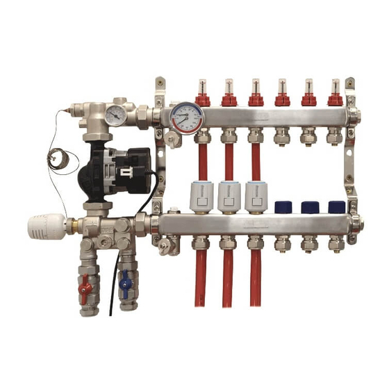
Overview °F °C WHS-M-S3-MIX Mixing unit Capillary Thermostat - Secondary by-pass Sensor Primary by-pass Circulator Isolation Valve Primary Isolation Valve Thermometer - - Flow Secondary Flow Primary Isolation Valve - Grundfos UPM3 Return 25/70 - 130 Circulator Primary Supply Adaptors Capillary Thermostat - 1”G to 22mm Actuator... - Page 9 Overview WHS-M-S3-08 Manifold assembly 1 - 5 l/min Flowmeter Fill/Drain Valve Flowmeter Locking Cap Mounting Brackets Manual Air Vent Electrothermic Actuator Thermomanometer Electrothermic Actuator Flow Arm Collar End Caps Commissioning Cap Return Arm...
-
Page 10: Dimensions
Dimensions °F °C • The Warmup WHS-M-S3-XX manifolds are available in various configurations ranging from 2 ports through to 12 ports. • The manifolds are delivered pre-assembled in the mounting brackets with flow gauges, drain/fill valves, air vents, end caps and dual master gauge. - Page 11 Dimensions • The manifold can either be used as a standalone setup, or can be adapted with a Warmup WHS-M-S3-MIX mixing unit providing regulated temperature control enabling tailored system performance. Width/No. of Ports NOTE: All measurements are in millimetres (mm) unless otherwise...
-
Page 12: Step 1 - Location Considerations
Step 1 - Location Considerations Identify a suitable mounting location for the Warmup Manifold. The location should meet the following requirements; • The surface on to which it is to be mounted should be: • Structurally sound and capable of bearing the load imposed by the manifold •... -
Page 13: Step 2 - Assembly
Step 2 - Assembly - Mixing Unit The Warmup WHS-M-S3-MIX Mixing Unit is required for all installations where the temperature of the water provided by the heat source exceeds the design water temperature of the floor heating system. This includes all heat sources which intermittently ‘over heat’ due to sterilisation cycles or uncontrolled heating. - Page 14 Adding the Warmup WHS-M-S3-VALVES kit allows for the manifold system to be easily isolated from the primary pipework/heat source. Warmup recommends a minimum of 22mm for the primary pipework. NOTE: Loose nut fittings only required if connecting primary pipework directly to manifold.
- Page 16 Step 2 - Assembly - Primary Pipework It is recommended the supply connections to the manifold are direct from the primary heating circuit, prior to any zone valves or control by other emitters or devices. Interlock should be established between the underfloor heating and the heat source.
- Page 17 Step 2 - Assembly - Secondary Pipework When preparing the pipework for connection to the manifold the end of the pipe must be cut cleanly with a suitable pipe cutter, and all swarf removed, to ensure a tight seal against the spigot is maintained. All circuit lengths should be recorded as accurately in the commissioning log on page 36 as possible to ensure correct commissioning of the system.
-
Page 18: Step 3 - Circuit Purging & Filling
Step 3 - Circuit Purging & Filling °F °C It is important that the manifold and connected circuits are purged prior to calibrating the system, to remove any air left in the pipework following install. The caps fitted to the fill/drain valves functions as a key to open and close both the valves and the manual air vents. - Page 19 Step 3 - Circuit Purging & Filling °F °C • Turn on the water supply and • Open first circuits return valve °F °C open both fill/drain valves. followed by its flow valve. °F °C °F °C • Purge until discharge water •...
-
Page 20: Step 4 - Pressure Testing
Step 4 - Pressure Testing The pressure test must be completed while the pipes are fully accessible and before any screed or floor deck has been laid. The pressure test is an important step to prove the integrity of the system, ensuring nothing has been damaged during the install. - Page 21 Isolate the leaking circuit • Locate and repair the leak • Repeat the pressure test If you are still experiencing problems, please contact Warmup NOTE: If a repair kit is used, ensure to record its location in the commissioning log.
-
Page 22: Step 5 - Circuit Balancing
Step 5 - Circuit Balancing If the Warmup Mixing Unit is installed follow the full set of instructions below. If the Warmup Mixing unit is not installed, please commission the primary circuit and proceed directly to step 8. °F °C °F... - Page 23 Determining your flow-meter settings If your system has been designed by the Warmup Projects Division, the required flow-rates will be specified on the Working Drawings used to install the system. In the absence of a design, the table below provides ‘typical’ flow rates, based on using a common floor construction with consistent loading throughout.
-
Page 24: Step 6 - Actuator Mounting
Actuator Mounting °F °C Adding Warmup WHS-M-S3-ACT230 actuators to the manifold enables individual zone control of the heating system. The Warmup actuators are amongst the most energy efficient UFH actuators available, using just 1W of power. • Remove isolating caps by •... -
Page 25: Step 7 - Circulator Mode Setting
LED’s are displaying the correct mode, let go of the push button. Repeat as necessary to select Constant Pressure Curve 3. NOTE: Warmup recommends enabling the key lock once the correct mode has been set to prevent tampering. -
Page 26: Step 8 - Capillary Thermostat Mounting
Options for setting the temperature of the thermostatic head If your system has been designed by the Warmup Projects Division, adjust the thermostatic head to produce the temperature specified on the Working Drawings used to install the system. -
Page 27: Step 9 - Temperature Settings
Step 9 - Temperature Settings Maximum Recommended Floor Construction Temperature Screed Floors 55 °C Timber Floors 60 °C All other Floors See manufactures specifications Limiting temperature control adjustment • Remove the cap from the • Rotate the thermostatic head thermostatic head, using a flat to the maximum permitted blade screwdriver. -
Page 28: Step 10 - Initial Heating Cycle
Step 10 - Initial Heat Cycle To prevent damage to floors, BS EN1264 specifies the following commissioning procedures: • Screeds should not be heated until they have fully cured. The minimum curing periods proposed for various screed types are specified below. Minimum Length of Time Before Screed Type Initial Heat Cycle... -
Page 30: Troubleshooting
Performance Troubleshooting ISSUE 1 - No heat to any zone Symptom Problem Solution Ensure the UFH controls are programmed correctly, and the UFH system not turning on heat source is able to provide hot water for the programmed period Ensure at least one thermostat Heat source or UFH circulator not is demanding heat and that the operating correctly... - Page 31 Performance Troubleshooting Detailed Troubleshooting 1. Check thermostat/controls are set ‘on’ 2. Check the heat source is operating and supplying heat to the UFH No heat in any zone system 3. Check the primary isolation valves are open 4. Check the mixing unit bypass is closed 5.
- Page 32 Notes _____________________________________ _____________________________________ _____________________________________ _____________________________________ _____________________________________ _____________________________________ _____________________________________ _____________________________________ _____________________________________ _____________________________________ _____________________________________ _____________________________________ _____________________________________ _____________________________________ _____________________________________ _____________________________________ _____________________________________ _____________________________________ _____________________________________ _____________________________________ _____________________________________ _____________________________________ _____________________________________ _____________________________________ _____________________________________ _____________________________________ _____________________________________ _____________________________________ _____________________________________ _____________________________________ _____________________________________ _____________________________________ _____________________________________ _____________________________________ _____________________________________...
-
Page 33: Layout Plan
Layout Plan NOTE: Draw a plan showing the layout and location of the heating circuits... -
Page 34: Commissioning Log
Commissioning Log Installer Details Plumber Electrician Name: Name: Company: Company: Address: Address: Postcode: Postcode: Tel: Tel: Email: Email: Project Ref: Project Ref: Installation Details Manifold Temperature Purged and Pressure Test Circuits Fully Location Setting Filled ? Completed ? Balanced ? Operational Circuit Room... - Page 35 Notes _____________________________________ _____________________________________ _____________________________________ _____________________________________ _____________________________________ _____________________________________ _____________________________________ _____________________________________ _____________________________________ _____________________________________ _____________________________________ _____________________________________ _____________________________________ _____________________________________ _____________________________________ _____________________________________ _____________________________________ _____________________________________ _____________________________________ _____________________________________ _____________________________________ _____________________________________ _____________________________________ _____________________________________ _____________________________________ _____________________________________ _____________________________________ _____________________________________ _____________________________________ _____________________________________ _____________________________________ _____________________________________ _____________________________________ _____________________________________ _____________________________________...
-
Page 36: Warranty
It is expressly agreed that the sole remedies under this limited warranty shall be at the discretion of Warmup, plc. to either: issue a refund, repair or replace any article which is proven to be defective. Any and all allowances made... - Page 37 Warmup product installation manual; 6. remain in their original installed location 7. do not show evidence of accidental damage, misuse, lack of care, tampering, or repair or modification without the prior written approval of Warmup plc.
-
Page 38: Technical Specifications
Technical Specifications TECHNICAL SPECIFICATIONS - Manifold MATERIAL 304 Stainless Steel PORTS AVAILABLE 2 - 12 TEMPERATURE RANGE -5°C to +60°C MAX OPERATING PRESSURE 6 Bar MAX TEST PRESSURE 10 Bar ADJUSTMENT RANGE 0 - 5 l/min MEASURING ACCURACY ±10% (of highest nominal value) MANIFOLD ARM DIMENSIONS 40 mm x 40 mm PIPE FITTING CENTRES... - Page 39 Technical Specifications TECHNICAL SPECIFICATIONS - Actuators OPERATING VOLTAGE 220-240 V AC 50/60Hz OPERATING TEMPERATURE 0 to +60 °C POWER DE-ENERGIZED POSITION Normally Closed INRUSH CURRENT max. 550 mA STROKE 4 mm IP RATING IP54 STORAGE TEMPERATURE -25 to 60 °C...
- Page 40 Web: www.warmup.co.uk Email: uk@warmup.com Tel: 0345 345 2288 Fax: 0345 345 2299 The WARMUP word and associated logos are trade marks. © Warmup Plc. 2016 – Regd. TM Nos. 1257724, 4409934, 4409926, 5265707. E & OE. v03-1216 Hydronic www.warmup.co.uk Heating System...
Need help?
Do you have a question about the WHS-M-S3-Series and is the answer not in the manual?
Questions and answers