Table of Contents
Advertisement
Available languages
Available languages
Quick Links
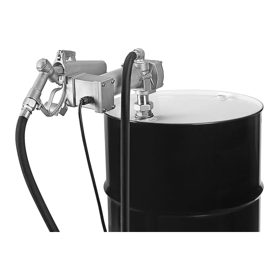
H-7193
FUEL TRANSFER PUMP
TOOLS NEEDED
10 mm Wrench
Adjustable Wrench
Pump and Motor Assembly
Hose
1.
Wrap PTFE tape around the male threads of the
elbow, hose end fitting and suction tube to ensure a
leakproof connection.
2. Unscrew nut and attach on/off switch. (See Figure 1)
3. Using a 10 mm wrench, remove the two bolts above
the on/off switch and reattach along with the nozzle
holder. (See Figure 1)
Figure 1
PAGE 1 OF 9
1-800-295-5510
uline.com
PARTS
Nozzle Holder
On/Off Switch
Wire Connecting
Nozzle
Adapter
ASSEMBLY
On/Off Switch
Nozzle Holder
Elbow
Power Cord
4. Hand tighten elbow onto pump outlet. Once no
longer able to hand tighten, use a wrench for 1/2
of an additional turn. (See Figure 2)
Figure 2
5. Fasten bung nut onto 2" opening of drum or tank.
(See Figure 3)
Figure 3
Para Español, vea páginas 4-6.
Pour le français, consulter les pages 7-9.
Suction Tube
PTFE Tape
Bung Nut
Elbow
Bung Nut
0621 IH-7193
Advertisement
Table of Contents

Related Manuals for U-Line H-7193


Summary of Contents for U-Line H-7193
- Page 1 Para Español, vea páginas 4-6. Pour le français, consulter les pages 7-9. H-7193 1-800-295-5510 uline.com FUEL TRANSFER PUMP TOOLS NEEDED 10 mm Wrench Adjustable Wrench PARTS Pump and Motor Assembly Nozzle Holder On/Off Switch Elbow Suction Tube Wire Connecting Power Cord...
- Page 2 ASSEMBLY CONTINUED 6. Connect two halves of the suction tube. 10. Attach the other end of the hose to the fuel nozzle. (See Figure 4) Tighten with adjustable wrench. (See Figure 8) Figure 4 NOTE: For shorter drums/tanks use only top portion of suction tube.
-
Page 3: Pump Operation
OPERATION PRIMING NOTE: Filed wiring shall comply with requirement stated article 501 in National Electrical Code NOTE: Pump should be primed prior to each use. (NEC) for Class I, Division 1 Location. 1. To prime, remove elbow from pump outlet. ELECTRICAL DIAGRAM FOR DC MOTOR 2. -
Page 4: Herramientas Necesarias
H-7193 800-295-5510 uline.mx BOMBA PARA TRANSFERIR COMBUSTIBLES HERRAMIENTAS NECESARIAS Llave de 10 mm Llave Ajustable PARTES Interruptor Portaboquilla Codo Tubo de Succión Ensamble de Bomba y Motor Encendido/Apagado Cinta de PTFE Tapón Adaptador de Cable Manguera Boquilla Roscado Cable de Conexión... - Page 5 CONTINUACIÓN DE ENSAMBLE 6. Conecte las dos mitades del tubo de succión. 10. Coloque el otro extremo de la manguera en la (Vea Diagrama 4) boquilla para combustible. Apriete con la llave ajustable. (Vea Diagrama 8) Diagrama 4 NOTA: Solo utilice la parte superior del tubo de succión para tambos o tanques más bajos.
-
Page 6: Funcionamiento De La Bomba
FUNCIONAMIENTO PREPARACIÓN NOTA: El cableado de campo debe cumplir con el requisito establecido en el artículo 501 NOTA: La bomba se debe preparar antes de cada uso. del Código Nacional de Electricidad (NEC) (EUA) para Clase I, Ubicación División 1. Para preparar, retire el codo de la salida de la bomba. -
Page 7: Outils Requis
H-7193 1-800-295-5510 uline.ca POMPE DE TRANSFERT DE CARBURANT OUTILS REQUIS Clé de 10 mm Clé ajustable PIÈCES Support de buse Commutateur Coude Tube de succion Ensemble pompe et moteur marche/arrêt Adaptateur de Cordon Ruban Écrou de connexion des câbles Tuyau... - Page 8 MONTAGE SUITE 6. Connectez les deux moitiés du tube de succion. 10. Raccordez l'autre extrémité du tuyau à la buse. (Voir Figure 4) Serrez plus fermement à l'aide d'une clé ajustable. (Voir Figure 8) Figure 4 REMARQUE : Pour les barils/réservoirs de taille réduite, utilisez uniquement la partie supérieure du tube de succion.
-
Page 9: Fonctionnement De La Pompe
FONCTIONNEMENT AMORÇAGE REMARQUE : Le câblage en existence doit être conforme à l'exigence indiquée dans l'article REMARQUE : La pompe doit être amorcée 501 du Code national de l'électricité pour les avant chaque utilisation. emplacements de classe 1, division 2. Pour amorcer, retirez le coude de la sortie de pompe.
Need help?
Do you have a question about the H-7193 and is the answer not in the manual?
Questions and answers