Table of Contents
Advertisement
Quick Links
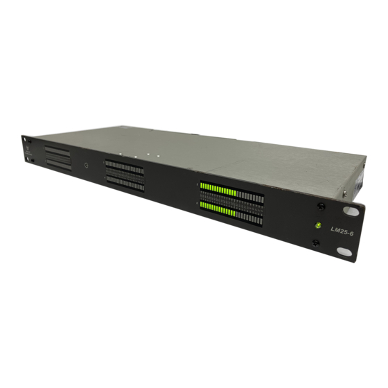
LM25 Analog Series
"Mini" Phoenix Input Connectors, and
25-Segment LED Bargraph Level Meters
Title and Contents ...........................................................
Introduction.............................................................................................
Description and Features ......................................................................
Applications and Specifications ............................................................
Rear and Front Panel Configurations .....................................................
Section 2: Operation .......................................................
Installation ............................................................................................
Front Panel Features .............................................................................
Rear Panel Features ...............................................................................
Section 3: Technical Information .................................
Level Meter Internal 10-Position DIP Switch Settings ..........................
Level Meter DIP Switch Locations ........................................................
Level Meter Alternate Scales .................................................................
LM25 Analog Interconnect Block Diagram ...........................................
© 2004 Wohler Technologies Inc. ALL rights reserved
1U Level Meter Units
Four, Six, or Eight Channels with
Document P/N 821612 Rev-A
User Manual
CONTENTS
ECO-2668 (10/13/04)
1
2
3
4
5
6
7
9
10
12
15
16
17
18
19
Advertisement
Table of Contents

Related Manuals for Wohler LM25 Analog Series


Summary of Contents for Wohler LM25 Analog Series
-
Page 1: Table Of Contents
Section 3: Technical Information ......... Level Meter Internal 10-Position DIP Switch Settings ......Level Meter DIP Switch Locations ............Level Meter Alternate Scales ..............LM25 Analog Interconnect Block Diagram ........... ECO-2668 (10/13/04) © 2004 Wohler Technologies Inc. ALL rights reserved... -
Page 2: Introduction
Introduction Congratulations on your selection of a Wohler Technologies product. We are confident it represents the best performance and value available, and we guarantee your satisfaction with it. If you have questions or comments you may contact us at: Wohler Technologies, Inc. -
Page 3: Section 1: General Features And Specifications
LM25 Analog Series User Manual P/N 821612 Rev-A Section 1 General Features and Specifications Description Features Applications Specifications Rear and Front Panel Configurations © 2004 Wohler Technologies Inc. ALL rights reserved... - Page 4 LM25-8 Front Panel Description The LM25 Analog Series audio level metering units offer high-resolution level metering with four, six, or eight channels in a space- saving 1U rack-mountable enclosure. Standard input connectors for the LM26 Analog Series are "mini" Phoenix type terminal block connectors. Analog input connec- tor impedances are 27K Ω...
- Page 5 Section 1: General Features and Specifications Applications The LM25 Analog Series of level metering units are an adaptable and effective way to monitor any analog audio application. The following are some of the applications where an LM25 unit would prove valuable.
- Page 6 The following illustration shows the standard input connectors available for use in the four, six, and eight channel models. Mini-Phoenix Input Modular Section (standard) Below are illustrations showing the two standard configurations of the LM25 Analog Series rear panels. LM25-4 Rear Panel LM25-6 Rear Panel LM25-8 Rear Panel ©...
-
Page 7: Section 2: Operation
LM25 Analog Series User Manual P/N 821612 Rev-A Section 2 Operation Installation Front Panel Features Rear Panel Features © 2004 Wohler Technologies Inc. ALL rights reserved... - Page 8 LM25 Analog Series User Manual P/N 821612 Rev-A Section 2: Operation (This page left intentionally blank) © 2004 Wohler Technologies Inc. ALL rights reserved...
- Page 9 Audio Connections Connection of the audio feeds is straightforward. The system interconnect block diagrams located on page 19 may be referred to for clarification of the general signal paths into the LM25 Analog Series units. Electrical Interference As with any audio equipment, maximum immunity from electrical interference requires the use of shielded cable; however, satisfac- tory results can sometimes be obtained without it.
- Page 10 Section 2: Operation Front Panel Features Please refer to Figure-2a on the following page to familiarize yourself with the front panel features of the LM25 Analog Series units. The following sections describe these functions and are referenced, by number, to Figure-2a.
- Page 11 LM25 Analog Series User Manual P/N 821612 Rev-A Section 2: Operation Figure-2a: Front Panel Features © 2004 Wohler Technologies Inc. ALL rights reserved...
-
Page 12: Rear Panel Features
Section 2: Operation Rear Panel Features Please refer to Figure-2b on the following page to familiarize yourself with the rear panel features of the LM25 Analog Series units. The following sections describe these features and are referenced, by letter, to Figure-2b. - Page 13 LM25 Analog Series User Manual P/N 821612 Rev-A Section 2: Operation Figure-2b: Rear Panel Features © 2004 Wohler Technologies Inc. ALL rights reserved...
- Page 14 LM25 Analog Series User Manual P/N 821612 Rev-A Section 2: Operation (This page left intentionally blank) © 2004 Wohler Technologies Inc. ALL rights reserved...
-
Page 15: Section 3: Technical Information
LM25 Analog Series User Manual P/N 821612 Rev-A Section 3 Technical Information Level Meter Internal 10-Position DIP Switch Settings Level Meter DIP Switch Locations Level Meter Alternate Scales LM26 Analog Interconnect Block Diagram © 2004 Wohler Technologies Inc. ALL rights reserved... - Page 16 LM25 Analog Series User Manual P/N 821612 Rev-A Operation Level Meter Internal 10-Position DIP Switch Settings This 10-position DIP switch is accessed by removing the top cover of the LM unit and is located on the 919174 PCB (the same PCB on which the 6-position rear panel DIP switch is located).
- Page 17 LM25 Analog Series User Manual P/N 821612 Rev-A Level Meter DIP Switch Locations Rear Panel Level Meter 6- Position DIP Switch Module (see page 12) Figure-3a: Internal Level Meter 10-Position DIP Switch DIP Switch Locations on Module (see page 16)
- Page 18 LM25 Analog Series User Manual P/N 821612 Rev-A Section 3: Technical Information Level Meter Alternate Scales The standard scale used on the ALM25 Analog Series of level meters is the Extended VU scale. However, if alternative scale characteristics are selected for the level meters by setting the Alternate Scale section of the Level Meter Internal 10-Position DIP switch (see page 16), it is recommended that a label with the appropriate scale be applied to the front panel LED bargraph level meters.
- Page 19 LM25 Analog Series User Manual P/N 821612 Rev-A Section 3: Technical Information © 2004 Wohler Technologies Inc. ALL rights reserved...
- Page 20 LM25 Analog Series User Manual P/N 821612 Rev-A NOTE: PCB layout and schematic support documentation is available upon request. Wohler Technologies, Inc. Wohler Technologies, Inc. 713 Grandview Drive 31055 Huntwood Avenue South San Francisco, CA 94080 Hayward, CA 94544 650 589-5676 Fax: 650 589-1355...
- Page 21 LM25 Analog Series User Manual P/N 821612 Rev-A Notes: © 2004 Wohler Technologies Inc. ALL rights reserved...
- Page 22 LM25 Analog Series User Manual P/N 821612 Rev-A Wohler Technologies, Inc. Wohler Technologies, Inc. 713 Grandview Drive 31055 Huntwood Avenue South San Francisco, CA 94080 Hayward, CA 94544 650 589-5676 Fax: 650 589-1355 Phone: (510) 870-0810 Fax: (510) 870-0811 web: www.wohler.com US Toll-Free: 1-888-596-4537 e-mail: support@wohler.com...
Need help?
Do you have a question about the LM25 Analog Series and is the answer not in the manual?
Questions and answers