Table of Contents
Advertisement
Quick Links
RF-BM-2340A2(I)
www.szrfstar.com
V1.0 - Sep., 2023
RF-BM-2340A2 And RF-BM-2340A2I CC2340R5
BLE5.3 or ZigBee 3.0 Wireless Module
Version 1.0
Shenzhen RF-star Technology Co., Ltd.
st
Sep. 1
, 2023
All rights reserved. Those responsible for unauthorized reproduction will be prosecuted.
Shenzhen RF-star Technology Co., Ltd.
Page 1 of 27
Advertisement
Table of Contents

Related Manuals for RF-Star RF-BM-2340A2 CC2340R5


Summary of Contents for RF-Star RF-BM-2340A2 CC2340R5
- Page 1 V1.0 - Sep., 2023 RF-BM-2340A2 And RF-BM-2340A2I CC2340R5 BLE5.3 or ZigBee 3.0 Wireless Module Version 1.0 Shenzhen RF-star Technology Co., Ltd. Sep. 1 , 2023 All rights reserved. Those responsible for unauthorized reproduction will be prosecuted. Shenzhen RF-star Technology Co., Ltd.
-
Page 2: Device Overview
- Operating temperature: -40 °C to +85 °C - 1 × UART - Storage temperature: -40 °C to +125 °C - 1 × SPI - Frequency range: 2360 MHz ~ 2510 MHz - 1 × I Shenzhen RF-star Technology Co., Ltd. Page 2 of 27... -
Page 3: Applications
• Gaming • Thermostat • Electronic and robotic toys • Wireless environmental sensor • Wearables (non-medical) • Fire safety system • Smart trackers • Smoke and heat detector • Smart clothing Shenzhen RF-star Technology Co., Ltd. Page 3 of 27... -
Page 4: Functional Block Diagram
I: IPEX Connector IC Code Company Name CC2340R5 4*4 Version RF-STAR Module Version The A HW Version Chipset Wireless Type Bluetooth Module CC2340 Series Figure 2. Part Number Conventions of RF-BM-2340A2(I) Shenzhen RF-star Technology Co., Ltd. Page 4 of 27... -
Page 5: Table Of Contents
5.6 Basic Operation of Hardware Design ...................... 20 5.7 Trouble Shooting .............................. 21 5.7.1 Unsatisfactory Transmission Distance ..................21 5.7.2 Vulnerable Module ..........................21 5.7.3 High Bit Error Rate ..........................21 5.8 Electrostatics Discharge Warnings ......................22 Shenzhen RF-star Technology Co., Ltd. Page 5 of 27... - Page 6 RF-BM-2340A2(I) www.szrfstar.com V1.0 - Sep., 2023 5.9 Soldering and Reflow Condition ......................... 22 6 Optional Package Specification ..........................24 7 Revision History ................................24 8 Contact Us ..................................27 Shenzhen RF-star Technology Co., Ltd. Page 6 of 27...
-
Page 7: Module Configuration And Functions
RF-BM-2340A2: 16.58 mm × 11.19 mm × 2.10 mm Dimension RF-BM-2340A2I: 15.20 mm × 11.19 mm × 2.10 mm RF-BM-2340A2: PCB antenna Type of Antenna RF-BM-2340A2I: IPEX connector or half-hole ANT pin -40 ℃ ~ +85 ℃ Operating Temperature Shenzhen RF-star Technology Co., Ltd. Page 7 of 27... -
Page 8: Module Pin Diagram
(JTAG_TMSC), high-drive capability GPIO, SWD interface: clock(JTAG_TCKC), high- SWDCK DIO17_SWDCK Digital drive capability RESET RSTN Digital Reset, active low. Internal pullup. DIO13 DIO13 Digital GPIO DIO11 DIO11 Digital GPIO Ground Ground Shenzhen RF-star Technology Co., Ltd. Page 8 of 27... - Page 9 Digital or Analog GPIO, analog capability DIO12 DIO12 Digital GPIO, high-drive capability None connect Ground Ground, for RF-BM-2340A2I only External ANT output pin, for RF-BM-2340A2I only Ground Ground, for RF-BM-2340A2I only Shenzhen RF-star Technology Co., Ltd. Page 9 of 27...
-
Page 10: Pin Peripheral Singal Descriptions
ADC channel 2 input HP ADC channel 1 input. ADC external ADC1/AREF+ DIO6 DIO6_A1 voltage reference, positive terminal HP ADC channel 0 input. ADC external Reference ADC0/AREF- DIO7 DIO7_A0 voltage reference, negative terminal Shenzhen RF-star Technology Co., Ltd. Page 10 of 27... - Page 11 SPI PICO (MOSI) SPI0PICO DIO16 DIO16_SWDIO DIO19 DIO19 DIO17 DIO17_SWDCK DIO24 DIO24_A7 I2C0SCL C clock data DIO25 DIO25_A6 DIO6 DIO6_A1 DIO8 DIO8 DIO12 DIO12 I2C0SDA C data DIO16 DIO16_SWDIO DIO0 DIO0_A5 Shenzhen RF-star Technology Co., Ltd. Page 11 of 27...
- Page 12 DIO21_A10 GPIO22 DIO22 DIO22_A9 GPIO23 DIO23 DIO23_A8 GPIO24 DIO24 DIO24_A7 GPIO25 DIO25 DIO25_A6 GPIO0 DIO0 DIO0_A5 GPIO1 DIO1 DIO1_A4 GPIO2 DIO2 DIO2_A3 GPIO5 DIO5 DIO5_A2 GPIO6 DIO6 DIO6_A1 GPIO7 DIO7 DIO7_A0 Shenzhen RF-star Technology Co., Ltd. Page 12 of 27...
-
Page 13: Specifications
3.2 Handling Ratings Table 7. Handling Ratings of RF-BM-2340A2(I) Items Condition Typ. Max. Unit Min. Storage Temperature Tstg +125 ℃ Human Body Model ±1000 Moisture Sensitivity Level Charged Device Model ±500 Shenzhen RF-star Technology Co., Ltd. Page 13 of 27... -
Page 14: Internal 32.768 Khz Crystal Setting
32.768 kHz crystal by default, pls see the details below: Therefore, in order no problem during debugging, pls modify the default crystal setting to the internal crystal LF RCOSC as follows: Shenzhen RF-star Technology Co., Ltd. Page 14 of 27... -
Page 15: Application, Implementation, And Layout
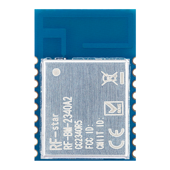
RF-BM-2340A2(I) www.szrfstar.com V1.0 - Sep., 2023 5 Application, Implementation, and Layout 5.1 Module Photos RF-BM-2340A2 RF-BM-2340A2I Figure 3. Photos of RF-BM-2340A2(I) 5.2 Recommended PCB Footprint RF-BM-2340A2 Shenzhen RF-star Technology Co., Ltd. Page 15 of 27... -
Page 16: Schematic Diagram
RF-BM-2340A2(I) www.szrfstar.com V1.0 - Sep., 2023 RF-BM-2340A2I Figure 4. Recommended PCB Footprint of RF-BM-2340A2(I) 5.3 Schematic Diagram RF-BM-2340A2 Shenzhen RF-star Technology Co., Ltd. Page 16 of 27... -
Page 17: Reference Design
(2) Make sure that there is no signal line or copper foil in each layer below the antenna. (3) It is best to hollow out the antenna position in the following figure to ensure that the S11 of the module is minimally affected. Shenzhen RF-star Technology Co., Ltd. Page 17 of 27... -
Page 18: Antenna Output Mode Modification
Figure 5. Reference Design of the External Antenna Figure 6. Reference Design of the External Antenna Traces 2. The RF trace width and copper-clad spacing can be calculated by SI9000 software, and the impedance is controlled Shenzhen RF-star Technology Co., Ltd. Page 18 of 27... -
Page 19: Ipex Connector Specification
Figure 7. SI9000 Impedance Calculation Diagram 5.5.4 IPEX Connector Specification RF-BM-2340A2I module is integrated with the IPEX version 1 antenna seat, the specification of the antenna seat is as follows: Figure 8. Specification of Antenna Seat Shenzhen RF-star Technology Co., Ltd. Page 19 of 27... -
Page 20: Basic Operation Of Hardware Design
6. Assuming that there are devices with large electromagnetic interference around the module, which will greatly affect the module performance. It is recommended to stay away from the module according to the strength of the interference. If circumstances permit, appropriate isolation and shielding can be done. Shenzhen RF-star Technology Co., Ltd. Page 20 of 27... -
Page 21: Trouble Shooting
1. There are co-channel signal interferences nearby. It is recommended to be away from the interference sources or modify the frequency and channel to avoid interferences. 2. The unsatisfactory power supply may also cause garbled. It is necessary to ensure the power supply's reliability. Shenzhen RF-star Technology Co., Ltd. Page 21 of 27... -
Page 22: Electrostatics Discharge Warnings
3. If the extension wire or feeder wire is of poor quality or too long, the bit error rate will be high. 5.8 Electrostatics Discharge Warnings The module will be damaged by the discharge of static. RF-star suggests that all modules should follow the 3 precautions below: 1. - Page 23 RF-BM-2340A2(I) www.szrfstar.com V1.0 - Sep., 2023 Figure 10. Recommended Reflow for Lead-Free Solder Shenzhen RF-star Technology Co., Ltd. Page 23 of 27...
-
Page 24: Optional Package Specification
The default package method is . If you need the modules to be shipped by tape & reel, pls contact us in advance. Figure 11. Default Package by Tray Shenzhen RF-star Technology Co., Ltd. Page 24 of 27... - Page 25 RF-BM-2340A2(I) www.szrfstar.com V1.0 - Sep., 2023 Figure 12. Package by Tape & Reel Shenzhen RF-star Technology Co., Ltd. Page 25 of 27...
-
Page 26: Revision History
1. The document will be optimized and updated from time to time. Before using this document, please make sure it is the latest version. 2. To obtain the latest document, please download it from the official website: www.rfstariot.com and www.szrfstar.com. Shenzhen RF-star Technology Co., Ltd. Page 26 of 27... -
Page 27: Contact Us
RF-BM-2340A2(I) www.szrfstar.com V1.0 - Sep., 2023 8 Contact Us SHENZHEN RF-STAR TECHNOLOGY CO., LTD. Shenzhen HQ: Add.: Room 502 ~ 503, Podium Building No. 12, Shenzhen Bay Science and Technology Ecological Park, Nanshan District, Shenzhen, Guangdong, China, 518063 Tel.: 86-755-8632 9829 Chengdu Branch: Add.: N2-1604, Global Center, North No.
Need help?
Do you have a question about the RF-BM-2340A2 CC2340R5 and is the answer not in the manual?
Questions and answers