
Related Manuals for Whirlpool WFRB1054BHG2


Summary of Contents for Whirlpool WFRB1054BHG2
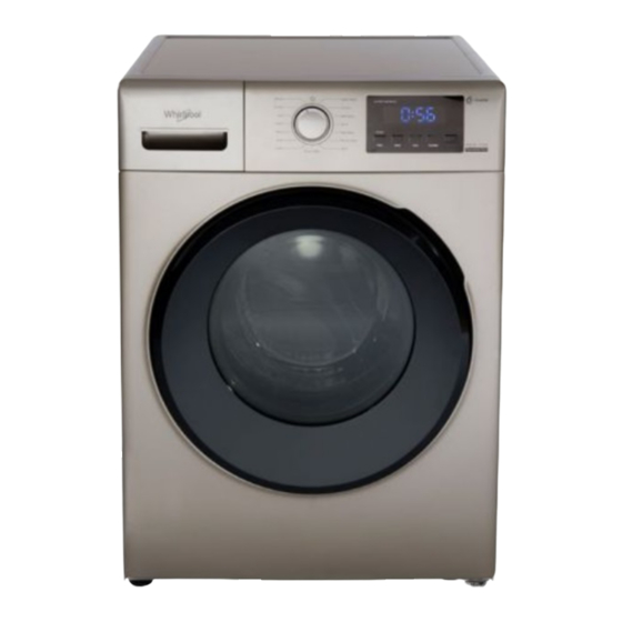
- Page 1 [键入文字] SERVICE MANUAL for Lite WFRB1054BHG2 WFRB954 BHG2 WFRB852BHG2 WFRB752BHW2 front load drum washer Models: WFRB1054BHG2 WFRB954 BHG2 WFRB852BHG2 WFRB752BHW2 Appearance, Color, Functions, Parameters of the Washing Machines...
- Page 2 [键入文字] WFRB1054BHG2 WFRB954BHG2 WFRB802BHG2 WFRB752BHW2 Gold body+ Black Gold body+ Gold body+ White body+ Cabinet color door Black door Black door White door Product picture √ √ √ √ AC motor × × × × Air wash eradicate odors ×...
- Page 3 [键入文字] Contents Product Specification Structure Functions setting and display Explosive decomposition diagram The machine decomposition step Use precautions...
- Page 4 [键入文字] 1.Product specification Specifications of major components Part name Specification Part name Specification Material:PP+GF30 Out tub (total length of front and Back cover SGCC, T1.0 back) Material:PCM board, Front cover Buzzer Electric buzzer Temperature Resistance R(50°C)=19.73 kΩB four legs Sensor(for wash Parameter(25/85°C)= 3992K adjustable.
- Page 5 [键入文字] 2.Structure 1. Structure diagram(Detailed assembly drawings) 2 Waterway system Water inlet :Water inlet pipe―→Valve Assembly―→water inlet hose―→Pour Inlet―→Feed Hose―→Out Tub Drainage:Spin tub out tub―→Drain hose inside―→Drain pump―→Drain hose ― → V alve Assembly ― → w ater inlet hose ― → P our Inlet(Water inlet for pre-wash) Defoaming:Water inlet pipe...
- Page 6 [键入文字] 3.The buttons and functions setting and displaying 1、Control panel...
- Page 7 [键入文字] 2、Specs label...
- Page 8 [键入文字]...
- Page 9 [键入文字] 3、Various Functions...
- Page 10 [键入文字] 4、No Trouble Conditions...
- Page 11 [键入文字] 5、Trouble Shooting Guide...
- Page 12 [键入文字] 4. E xplosive decomposition diagram...
- Page 13 [键入文字] WFRB752BHW2 Part ID Part Name quantity 301G16A008942 top cover kit 301G11A003649 Connection Panel 301G42A010045 Water Sensor 301G802600006 door lock 301G11A005404 cabient front 301G17A005405 Drain pump cover 301G32A008394 Drain pump 3010143009140 301G99A005207 Transport bolt A-10 301G11A004081 cabient back Cover A-11 301G809000007 filter A-12...
- Page 14 [键入文字] 301G18A007443 Control Plate sticker 301G18A006639 Control Plate 70C03580 computer board 301G15A005688 outer door 301G15A003677 door glass 301G15A003676 inner door 301G152000008 door hook 301G15A003679 hinge cap 301G15A003678 door hinge 301G991000035 Screw 301G22A005134 front tub 301G15A003657 Outer Tub Gasket 301G99A004641 counterweight Screw 301G22A003856 lower counterweight 301G32A005375...
- Page 15 [键入文字] knob 301G18A003672 301G18A003665 Control Plate mirror Control Plate sticker 301G18A007434 Control Plate 301G16A007337 70C03580 computer board outer door 301G15A003675 301G15A003677 door glass 301G15A003676 inner door 301G152000008 door hook 301G15A003679 hinge cap 301G15A003678 door hinge 301G991000035 Screw 301G22A005134 front tub 301G15A003657 Outer Tub Gasket 301G99A004641...
- Page 16 Screw 301G90A003736 packing top 301G90A003735 packing side 301G90A003734 packing side 301G41A005411 packing bottom 301G90A003733 packing side 301G90A003732 packing side WFRB1054BHG2 Part ID Part Name quantity top cover kit 301G16A008932 301G11A003649 Connection Panel 301G801600003 Water Sensor 301G80A004827 door lock ...
- Page 17 [键入文字] Drain pump 3 01G32A008394 301G14A002672 301G99A005207 Transport bolt A-10 cabinet back Cover 3 01G11A002102 A-11 301G809000007 filter A-12 Cabinet 3 01G11A001404 A-13 301G31A003725 inlet valve A-14 301G31A007457 Pour Inlet Assembly Soap Box 3 01G31A007813 knob 301G18A003672 301G18A003665 Control Plate mirror...
- Page 18 [键入文字] 5.Complete machine decomposition step Photos Process Attention 1. Please confirm the 1.Use bolts for transportation empty of the washing machine before Use a wrench to loosen the disassembling. transport fixing bolts Please disconnect the pieces), shake the bolt to power plug before the right and left, pull it out, disconnecting the...
- Page 19 [键入文字] 3.Control panel Remove the upper part of the control panel and the four fastening screws under the shelf 。 Hold down the tab at the detergent box and pull outwards to remove the detergent box 。 C Remove the two screws from detergent box, remove the cable tie, and...
- Page 20 [键入文字] 4. Display board After the control board is fixed, the two screws of the display board box are dropped, and the six buckles are removed to remove the display board box. Remove the screws that hold display board, remove harness connector, and remove the display board...
- Page 21 [键入文字] 5.Door Remove the 2 screws on the hinge to remove the door 6.Front cover Remove the 2 top and 3 bottom fastening screws on the front cover Pull down the tight spring Unplug harness connector, then the front cover can be removed 7.Door lock Remove the 2 screws on the front cover to fix the...
- Page 22 [键入文字] Water inlet and inlet valve assembly A R emove fastening screws for the valve and inlet box assembly on the back of the cabinet B.Remove the 1 screw from the illustration W ith the vise clamped off C. the water inlet hose, cut off the cable tie, unplug the harness connector, remove the water inlet hose and...
- Page 23 [键入文字] 9Filter removal Remove the two screws on the rear side and remove the filter harness connector. 10 Upper counterweight and front counterweight A U se a special tool to remove the three screws shown to remove the upper counterweight and the front counterweight...
- Page 24 [键入文字] 12.Rear cover A. R emove the six fastening screws shown illustration and remove the back cover 13.Motor Remove the 2 screws and belt screws of the fixed motor, unplug harness connectors, and cut off the cable tie to remove motor (the drive board...
- Page 25 [键入文字] Remove the 3 screws that hold the drive plate and unplug rear wire harness insert. The drive plate can be removed. C Reactor removal: Remove 2 screws on the driver board cover to remove the reactor 16.3D Sensor After the washing machine is dumped, the two screws of the 3D sensor screw are lowered and the connected...
- Page 26 [键入文字] 17.Drainage pump assembly A Open the emergency filter cover pull out the emergency drain B Remove the 4 screws C Tilt the washing machine, remove the left and right tube cards harness inserts from the bottom, and remove the drain pump.
- Page 27 [键入文字] 19.Components outside the tub A Remove the screws and retaining springs that fix the water level sensor vent hose, remove the vent hose, pull harness connector, and separate it from the tub Remove the temperature sensor and other connectors Remove 3 shock absorbers and remove the suspension...
- Page 28 [键入文字] 20. Out tub When doing this operation, please Two or three people work attention your together to force the tub safety, and pay special assembly from lift attention to the installation springs on both sides and of the tub (recovery) must then pull it out of the box be installed in the shock place...
Need help?
Do you have a question about the WFRB1054BHG2 and is the answer not in the manual?
Questions and answers