Advertisement
Quick Links
Advertisement

Related Manuals for imovr OMEGA DENALI


Summary of Contents for imovr OMEGA DENALI
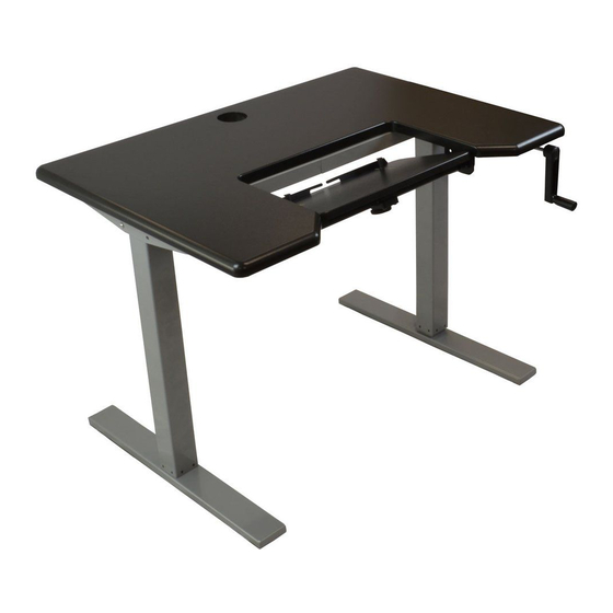
- Page 1 OMEGA DENALI Adjustable-Height Desk System INSTALLATION MANUAL V1.0...
-
Page 2: Before You Begin
BEFORE YOU BEGIN PROVIDED (19) M6 hexagonal (10) 5x20 mm (4) Foot Caps machine bolts Machine Screws (2) Hex Wrenches (2) Feet (Identical) (2) Support Arms Right and Left (2) Crossbars (Identical) (1) Crank Shaft (1) Crank Handle (1) Drive Shaft Right, Left, &... - Page 3 (2) Carriage bolts PLEASE READ THIS ONGRATULATIONS for purchasing an Omega DENALI™ adjustable-height desk system! We designed this product to be as easy as possible to assemble, but if you have any questions during the assembly process please contact our Customer Care team using the...
- Page 4 Be careful not to slide the table top while upside-down, to protect the laminate. THE base is designed to work with Omega Denali desk tops which include threaded insert nuts that remove any confusion or need to drill, the bit size to use, or how deep to drill.
- Page 5 ATTACH ARMS TO LEGS FOR THIS STEP ATTACH the left and right top arms to their respective lifting columns using four (4) M6 machine bolts for each top arm. Make sure the top support arms are facing outwards. Do not tighten these bolts all the way. ATTACH BASE TO TABLE TOP FOR THIS STEP EXTEND the base to the appropriate width, so...
- Page 6 INSERT DRIVE SHAFT FOR THIS STEP INSERT the two rods into the drive shaft. Position the drive shaft between the two legs and expand the drive shaft until the two rods are inserted into their respective legs. drive shaft aerial view of underside ATTACH CRANK TO ARM FOR THIS STEP INSERT the crank shaft into the crank gear...
- Page 7 FOR THIS STEP ASSEMBLE KEYBOARD PLATFORM ATTACH the two foot supports to the underside of the keyboard platform using three #10 1-1/4” flat head Phillips screws and three spacers per foot support. Position each set of spacers between the foot support and the underside of the keyboard platform.
- Page 8 FOR THIS STEP ATTACH KEYBOARD PLATFORM USING eight M5 20mm pan head machine screws, attach the mounting assembly and platform to the underside of the desk. Align the tube assembly by matching the four holes on each mounting bracket to the four insert nuts on both sides of the Omega cutout.
- Page 9 ATTACH KEYBOARD FENCE FOR THIS STEP TILT the Omega keyboard platform so that you can easily access both the top and bottom of the rear end of the platform. Using three #10 5/8” pan head Phillips, attach the keyboard fence to the back of the platform so that the built-in cable guide is facing up when the keyboard platform is flat.
-
Page 10: Troubleshooting
TROUBLESHOOTING IF one side of the Omega Denali is rising up or down but not the other, check that the drive shaft is connected to both legs. -
Page 11: Preventative Maintenance & Cleaning
WARRANTY THE OMEGA DENALI warranty coverage includes 5 years on table tops, and 2 years on the base. The following limitations apply: THIS WARRANTY only covers defects as specified herein and does not include defects or damages attributable to improper installation, misuse or normal surface weathering, or defects or damages caused by accidents or fire or other casualty or Acts of God, or any other causes or occurrences beyond the manufacturer’s control. -
Page 12: Specifications
THE 3” grommet holes provided in the OMEGA table tops are ideally sized for accepting the flush-mounted power socket “nodes.” iMovR HOURS: See www.iMovr.com/hours PHONE: (888) 208-6770 or (425) 999-3550 FAX: (425) 999-3550 E-MAIL: customercare@imovr.com LIVE CHAT: www.iMovR.com OMEGA DENALI INSTALLATION MANUAL PART NO. DO-IM-OD-INST...
Need help?
Do you have a question about the OMEGA DENALI and is the answer not in the manual?
Questions and answers