
Related Manuals for NewArc WFU12A-ILS


Summary of Contents for NewArc WFU12A-ILS
- Page 1 Newcastle Upon Tyne Powered by Tel. 0191 295 0111 sales@newarc.co.uk ® Newarc WFU12A-ILS Operational Manual NA9910630...
- Page 2 The RoHS Directive 2011/65/EU, entering into force 2 January 2013 Type of Equipment Wire feeder Brand name or trade mark Newarc Type designation etc. WFU12A-ILS Manufacturer or his authorised representative established within the EEA Name, address, telephone no Newarc Newcastle upon Tyne Phone: +44 (0)191 295 0111...
- Page 3 Never use broken or faulty welding helmets. Always ensure there are adequate protective screens or barriers to protect others from flash, glare and sparks from the welding area. Ensure that there are adequate warnings that welding or cutting is taking place. WFU12A-ILS...
- Page 4 In the case of electromagnetic problems, it is the responsibility of the user to resolve the situation. It may be necessary to shield the equipment and fit suitable filters on the mains supply. WFU12A-ILS...
- Page 5 BE AWARE OF SPARKS AND SPATTER DO NOT TOUCH THERMAL COMPONENTS! Wear protective clothing, such as leather Thermal components may cause severe burns gloves, Flame retardant overalls, boots and when in contact with unprotected skin. eyewear. WFU12A-ILS...
-
Page 6: Table Of Contents
Contents Preface General Introduction Technical Specifications Overview of Panel MF36 Overview of Panel MF37 Overview of Machine Installation Operation Fault Finding MF36 Fault Codes MF37 Fault Codes Maintenance Warranty Electrical Diagram Parts WFU12A-ILS... -
Page 7: Preface
This operating manual contains important information on the use, maintenance and safety of your Newarc product. Please read the manual carefully before using the equipment for the first time. For your own safety and that of your working environment, pay particular attention to the safety instructions in the manual. -
Page 8: Introduction
The simple front panel layout allows for ease of set up on CC or CV mode, and all functions are directly accessible by the multi function control knob and water proof push buttons. The WFU12A-ILS wire feed unit is designed to work with any welding power source working in constant current or constant voltage mode. -
Page 9: Technical Specifications
1.3 Technical Specifications Newarc WFU 12ILS Current Rating 400 amps @ 60% 300 amps @ 100% Wire Diameter 0.8mm - 2.4mm Max Wire Spool Size 20cm / 12” Wire Speed Range 0 - 23m/min Voltage Control CC (constant current) - Yes... -
Page 10: Overview Of Panel Mf36
If the optional current transducer LEM circuit is fitted • Wire Speed the displays also displays the c urrent (A) of the welding arc. Note: The wire speed setting is the maximum wire speed. The wire speed will change to help keep the welding condition. WFU12A-ILS WFU12A-ILS... - Page 11 4D is similar to 4T but with a delay time of 1 seconds before it latches on, this allows a quick tack weld feature in latch mode. Note! During welding the MF36 displays the voltage (U) of the welding arc. If the optional current transducer LEM circuit is fitted WFU12A-ILS...
-
Page 12: Overview Of Panel Mf37
1 seconds before it latches on, this allows a quick tack the MIG torch switch. Additional options weld feature in latch mode. Pressing the mode button (3) allows other options to be WFU12A-ILS displayed on the two displays and changed using the knob below the corresponding display. WFU12A-ILS... - Page 13 If the MF37 is left idling for more than 4 minutes the panel goes into standby made. This is indicated by a small red LED in display2 pulsing on and off. To reactivate the panel press or turn anything on the MF37 panel or press the MIG torch switch. WFU12A-ILS...
-
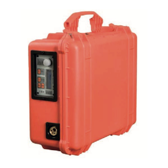
Page 14: Overview Of Machine
(if fitted), wire feed and gas flow until the required welding condition is achieved. When used with the Newarc power sources all the controls can be adjusted whilst welding without dam- aging the machine. - Page 15 (if fitted), wire feed and gas flow until the required welding condition is achieved. When used with the Newarc power sources all the controls can be adjusted whilst welding without damaging the machine.
-
Page 16: Installation
• When using the remote cable, the change in voltage will only be reflected on the display of the power source and not on the display of the feed unit. source and not on the display of the feed unit. WFU12A-ILS... - Page 17 Do not over-tighten this connection. Note! The pressure regulator should be set between approximately 3 and 5 bar for normal use. WFU12A-ILS...
-
Page 18: Operation
Voltage (V) Max Wire Speed (m/min) Additional Settings 1. Adjust the additional settings of Burn Back, Post Gas, Pre Gas and Slow Start as required. NOTE! Some features are available only in certain modes or with certain Front Panels. WFU12A-ILS... -
Page 19: Fault Finding
Power source set to MMA (constant current), either change power source to MIG (constant voltage) or set wire-feeder to constant current setting. When using the Wire-feeder in constant current mode, especially with flux-cored wires, it improves the welding characteristic if reverse polarity is used (torch -ve). WFU12A-ILS... -
Page 20: Mf36 Fault Codes
Call service. Warning 4 Gas valve not detected Check connections to gas valve Warning 5 Contactor not detected. Check connections to contactor Warning 6 Driver brake fault Call service Warning 7 Gas valve voltage. Check connection to gas valve. WFU12A-ILS... -
Page 21: Mf37 Fault Codes
Call service. Prob. 4 Gas valve not detected. Check connections to gas valve Prob. 5 Contactor not detected. Check connections to contactor Prob. 6 Driver brake fault Call service Prob. 7 Gas valve voltage. Check connection to gas valve. WFU12A-ILS... -
Page 22: Maintenance
Annually As per the three monthly schedule, plus: • Have the wire-feeder calibration checked, if necessary have the machine re-calibrated by a Newarc trained technician. WFU12A-ILS... -
Page 23: Warranty
Newarc Ltd warrants that its goods and services are guaranteed to meet the specific performance under the stated conditions of use. Newarc cannot be held responsible for general wear and tear or for failure occurring due to misuse or abuse arising out of circumstances outside the stated condi-tions of use. -
Page 24: Electrical Diagram
7. Electrical Diagram SECTION 6 — ELECTRICAL DIAGRAMS 6.1 - System Diagram WFU12A-ILS WFU12A-ILS... -
Page 25: Parts
8. Parts SECTION 7—PARTS BREAKDOWN 7.1 - Component Locations WFU12A-ILS WFU12A-ILS... - Page 26 SECTION 7—PARTS BREAKDOWN 7.1 - Component Locations WFU12A-ILS WFU12A-ILS...
- Page 27 NAM00022A Gas inlet stem NAM90992 Panel mounted remote socket harness EW3550PPW Panel mounted dix plug NAM90741 Earth Reference Lead NAM00379 6.3A Glass fuse (PCB Mounted) NAM00274 2A Glass fuse (PCB Mounted) NAM90991 Ribbon Cable Assembly NAM90990 PCB Wiring Harness WFU12A-ILS...
- Page 28 Unit 1, Whitehouse Industrial Estate, Whitehouse Road Newcastle upon Tyne NE15 6LN Tel: +44 (0)191 295 0111| Email: sales@newarc.co.uk | www.newarc.co.uk Powered by WFU12A-ILS www.newarc.co.uk ®...
Need help?
Do you have a question about the WFU12A-ILS and is the answer not in the manual?
Questions and answers