
Related Manuals for NewArc Viper 2000


Summary of Contents for NewArc Viper 2000
- Page 1 Powered by Newcastle Upon Tyne Tel. 0191 295 0111 sales@newarc.co.uk ® Newarc Viper 2000 Operational Manual NA9910307...
- Page 2 At the end of its serviceable life, this product should not be treated as household or general waste. It should be handed over to the applicable collection point for the recycling of electrical and electronic equipment, or returned to the supplier for disposal. VIPER 2000...
- Page 3 Never use broken or faulty welding helmets. Always ensure there are adequate protective screens or barriers to protect others from flash, glare and sparks from the welding area. Ensure that there are adequate warnings that welding or cutting is taking place. VIPER 2000...
- Page 4 In the case of electromagnetic problems, it is the responsibility of the user to resolve the situation. It may be necessary to shield the equipment and fit suitable filters on the mains supply. VIPER 2000...
- Page 5 BE AWARE OF SPARKS AND SPATTER DO NOT TOUCH THERMAL COMPONENTS! Wear protective clothing, such as leather Thermal components may cause severe burns gloves, Flame retardant overalls, boots and when in contact with unprotected skin. eyewear. VIPER 2000...
-
Page 6: Table Of Contents
Contents Preface General Introduction Technical Specifications Overview of Machine Installation Operation Fault Finding Welding Problems Maintenance Warranty Electriacl Diagram Parts VIPER 2000... -
Page 7: Preface
This operating manual contains important information on the use, maintenance and safety of your Newarc product. Please read the manual carefully before using the equipment for the first time. For your own safety and that of your working environment, pay particular attention to the safety instructions in the manual. -
Page 8: Introduction
1.2 Introduction The Viper 2000 is one of the smallest and lightest high frequency DC TIG control units available. This versatile unit operates from the open circuit voltage of any DC constant current power source or generator. It is also extremely easy to use and is powered directly from the power source without the need for any auxiliary supply cables. -
Page 9: Technical Specifications
1.3 Technical Specifications Newarc VIPER 2000 Input Voltage Range 40 -100 Volts Maximum Output Current 200 amps TIG Duty Cycle 100% @ 200amps Degree of Protection IP23 Dimensions (L x W x H) (mm) 322 x 127 x 210 Weight (kg) -
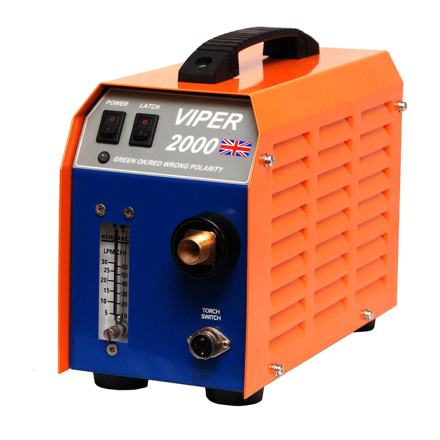
Page 10: Overview Of Machine
NOTE! Do not over tighten the control knob as damage may occur to the flow-meter valve seat, note that if the control knob is unscrewed too far air may enter the valve assembly and may cause porosity or contamination of the weld. VIPER 2000... - Page 11 Gas Control Gas pre-flow, the Viper 2000 provides pre and post timing of gas flow using an internal gas solenoid. When the torch switch is operated for the first time there will be 0.25-second purge of shielding gas before the contactor and arc ignition circuits are energized. This initial delay is to ensure that the argon lines and welding torch are purged of air before welding commences.
-
Page 12: Installation
2. Installation Positioning the Viper 2000 Postion the Viper 2000 on a clean dry base preferably above ground level. Ensure that the ventilation louvers on the side of the unit are not obstructed. Protect the machine against heavy rain. Frequently inspect the interconnection cables and welding torch and repair any defects immediately. -
Page 13: Operation
15 seconds the overload indicator will extinguish and the machine is ready to weld. • Turn the current control to the recommended setting for the size and type of welding electrode to be used. • When welding, adjust the Arc-force control to achieve the arc condition you require. VIPER 2000... -
Page 14: Fault Finding
Unit appears to be dead Ensure that both power source and Viper 2000 are switched on. If the power indictor is not lit then check for breaks in the power cables. If the power indicator is red then the power cables need to be reversed. If the power indicator is green then the power cables are correctly polarized. -
Page 15: Maintenance
• Check the condition of the welding output connectors, look for any signs of discoloration. This could be an indication of overheating and can be a cause of welding set failure. Annually As per the three monthly schedule, plus: Have the machines calibration checked, if necessary have the machine re-calibrated by a Newarc trained technician. VIPER 2000... -
Page 16: Warranty
Newarc Ltd warrants that its goods and services are guaranteed to meet the specific performance under the stated conditions of use. Newarc cannot be held responsible for general wear and tear or for failure occurring due to misuse or abuse arising out of circumstances outside the stated condi-tions of use. -
Page 17: Electriacl Diagram
7. Electrical Diagram SECTION 6 — ELECTRICAL DIAGRAMS 6.1 - System Diagram VIPER2000 VIPER 2000... -
Page 18: Parts
8. Parts VIPER 2000... - Page 19 HF inductor assembly NAM90499 Negative bus bar NAM90500 Positive bus bar NAM00026 Molded handle NAM00096 Mounting feet (4 per machine) Fuse 3.15 amp slow blow NAM00020 NAM00063 Torch switch plug Quote serial number of machine when ordering parts VIPER 2000...
- Page 20 Unit 1, Whitehouse Industrial Estate, Whitehouse Road Newcastle upon Tyne NE15 6LN Tel: +44 (0)191 295 0111| Email: sales@newarc.co.uk | www.newarc.co.uk Powered by www.newarc.co.uk ®...
Need help?
Do you have a question about the Viper 2000 and is the answer not in the manual?
Questions and answers