Table of Contents
Advertisement
Quick Links
UM11579
PCA9957HN-ARD evaluation board
Rev. 1 — 25 February 2021
Document information
Information
Content
Keywords
PCA9957HN, SPI, Arduino port, EVK, LED, LED driver
Abstract
The PCA9957HN-ARD evaluation board is a daughter card equipped with
Arduino ports, designated for easy test and design of the PCA9957HN IC, 24-
channel SPI serial bus 32 mA/5.5 V constant current LED driver. The board
is fully compliant with IMXRT1050-EVKB, LPCXpresso55S69 (LPC55S69-
EVK) and i.MX 8M Mini LPDDR4 EVK (8MMINILPD4-EVK) (8MMINID4-EVK),
including GUI software control. The board can be attached to any device
equipped with Arduino ports.
User manual
Advertisement
Table of Contents

Subscribe to Our Youtube Channel
Related Manuals for NXP Semiconductors UM11579


Summary of Contents for NXP Semiconductors UM11579
- Page 1 UM11579 PCA9957HN-ARD evaluation board Rev. 1 — 25 February 2021 User manual Document information Information Content Keywords PCA9957HN, SPI, Arduino port, EVK, LED, LED driver Abstract The PCA9957HN-ARD evaluation board is a daughter card equipped with Arduino ports, designated for easy test and design of the PCA9957HN IC, 24- channel SPI serial bus 32 mA/5.5 V constant current LED driver.
-
Page 2: Revision History
UM11579 NXP Semiconductors PCA9957HN-ARD evaluation board Revision History Table 1. Revision history Date Description 02/25/2021 Initial version Important Notice NXP provides the enclosed product(s) under the following conditions: This evaluation kit is intended for use of ENGINEERING DEVELOPMENT OR EVALUATION PURPOSES ONLY. It is provided as a sample IC pre-soldered to a printed circuit board to make it easier to access inputs, outputs, and supply terminals. -
Page 3: Introduction
PCA9957HN, a 24-channel SPI serial bus 32 mA, 5.5 V constant current LED driver produced by NXP Semiconductors. The evaluation board serves as a daughter card that can be connected through an Arduino port to various Arduino compatible (including original Arduino Uno R3) EVK/mother boards for the purpose of testing and measuring the characteristics of the PCA9957HN Device Under Test (DUT). -
Page 4: Finding Kit Resources And Information On The Nxp Web Site
NXP Semiconductors PCA9957HN-ARD evaluation board Finding Kit Resources and Information on the NXP Web Site NXP Semiconductors provides online resources for this evaluation board and its supported device(s) at http://www.nxp.com. The information page for the PCA9957HN-ARD evaluation board is at http:// www.nxp.com/PCA9957HN-ARD. -
Page 5: Getting Ready
UM11579 NXP Semiconductors PCA9957HN-ARD evaluation board Getting Ready Working with the PCA9957HN-ARD requires the kit contents, additional hardware, and a Windows PC workstation with installed software. 4.1 Kit contents • Assembled and tested evaluation board in an anti-static bag • Quick Start Guide 4.2 Assumptions... -
Page 6: Getting To Know The Hardware
UM11579 NXP Semiconductors PCA9957HN-ARD evaluation board Getting to Know the Hardware 5.1 PCA9957HN-ARD features • Combined Arduino port/Fuji connector for data and power • Multiple board connection in stack architecture • On-board LEDs for all 24 outputs of the DUT •... -
Page 7: Led Section
UM11579 NXP Semiconductors PCA9957HN-ARD evaluation board 5.3 LED section The PCA9957HN features twenty-four LED drivers (PWM controlled, current sink sources). Different LEDs are allocated to each output. The LEDs can be disconnected from the load with jumpers. Moreover, the RGB LED D16 has jumpers connected in parallel for short testing. -
Page 8: Arduino Port
UM11579 NXP Semiconductors PCA9957HN-ARD evaluation board because the control input is pulled up (high state) through R89. When a secondary board is inserted into the Fuji output connector, the U5 control input located on the first board is pulled down to ground through pin 3 of J46 and J47 of the next board. When the switch U5 (first board) is open, the signal path of the SPI is: MOSI (Arduino port) –... -
Page 9: Fuji Connectors
UM11579 NXP Semiconductors PCA9957HN-ARD evaluation board Table 2. The pin chart of Arduino connectors and their usage ...continued Note 3: A4 / SDA common line for J2 – 5 and J4 – 9. A5 / SCL common line for J2 – 6 and J4 – 10. -
Page 10: Not Populated Components
UM11579 NXP Semiconductors PCA9957HN-ARD evaluation board 5.9 Not populated components In the schematic diagram / board layout some components are not soldered on the board. Crystal X1 is one of the main DNP (Do Not Populate) components. X1 is missing because the project is designed to accommodate two DUTs from the same LED driver series (PCA9957, and PCA9959). - Page 11 UM11579 NXP Semiconductors PCA9957HN-ARD evaluation board Figure 3. The PCA9957HN-ARD board picture, top view (up) and bottom view (down) UM11579 All information provided in this document is subject to legal disclaimers. © NXP B.V. 2021. All rights reserved. User manual Rev. 1 — 25 February 2021...
-
Page 12: Installing And Configuring Software Tools
UM11579 NXP Semiconductors PCA9957HN-ARD evaluation board Installing and Configuring Software Tools PCA9957HN_ARD evaluation board is designed and built as a daughter board able to work in conjunction with a mother board equipped with an Arduino port. The board was built to be fully compatible with the following NXP Evaluation (EVK) boards: •... -
Page 13: Configuring The Hardware
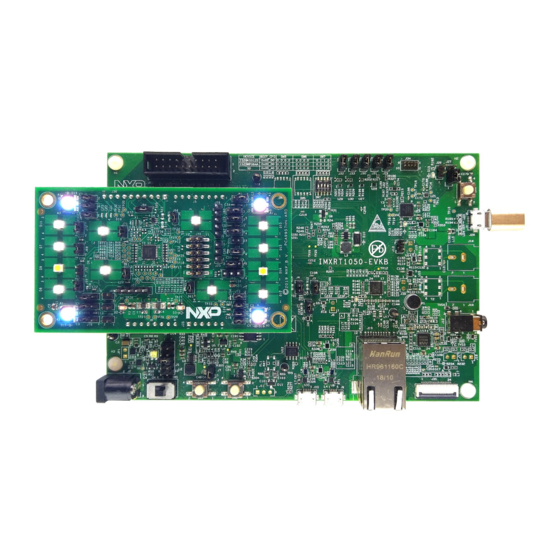
UM11579 NXP Semiconductors PCA9957HN-ARD evaluation board Configuring the Hardware 7.1 Using the PCA9957HN-ARD with an IMXRT1050 EVK board Figure 4 shows the required hardware for operation of the PCA9957HN-ARD daughter board with IMXRT1050 EVK. • One IMXRT1050 EVK board • One PCA9957HN-ARD daughter board •... -
Page 14: Using The Pca9957Hn-Ard With An Lpcxpresso55S69 Development Board
UM11579 NXP Semiconductors PCA9957HN-ARD evaluation board 1. On the IMXRT1050 EVK board, populate R278, R279, R280, R281 with zero-ohm resistors (0402 package) to link the SPI lines to the Arduino connector (see Note 2 in Section 5.6 "SPI bus"). 2. Using jumper J1, select the suitable power configuration for the EVK. - Page 15 UM11579 NXP Semiconductors PCA9957HN-ARD evaluation board However, using the P6 USB connector to connect the board to the PC simplifies the start-up operation because P6 is designated for debugging and the USB cable thus accomplishes two tasks at the same time: powering the board and serving as a data link between the EVK board and PC.
- Page 16 UM11579 NXP Semiconductors PCA9957HN-ARD evaluation board Figure 6. PCA9957HN-ARD daughter board and LPCXpresso55S69 mother board before starting The following steps describe how to assemble, power up, program, and operate the configuration shown in Figure 6 1. Insert the PCA9957HN-ARD daughter card to P16 – P19 connectors located on LPCXpresso55S69 development board (see the marked pins of P16 –...
-
Page 17: Using The Pca9957Hn-Ard With An I.mx 8M Mini Lpddr4 Evk Board
UM11579 NXP Semiconductors PCA9957HN-ARD evaluation board 2. Connect the development board using port P6 USB port of PC. 3. Install the LPCXpresso55S69 target firmware (download from the NXP site here read the EVK_Firmware_And_GUI_Install_Guide_For_Arduino_Boards.pdf instruction file); 4. Install GUI application on PC (see the instruction file called out in the previous step). - Page 18 UM11579 NXP Semiconductors PCA9957HN-ARD evaluation board pins on the PCA9957HD-ARD board and the 2 x 20 connector pins on the i.MX 8M Mini LPCCR4 EVK board. Figure 8 shows how these three boards are connected. This configuration consists of: • One i.MX 8M Mini LPDDR4 EVK board •...
- Page 19 UM11579 NXP Semiconductors PCA9957HN-ARD evaluation board 1. Insert the PCA9957HN-ARD onto the IMX8MMINI-IARD interposer board Arduino connectors (located on the top side). 2. Attach IMX8MMINI-IARD connector J1 (located on the bottom of the board) into J1003 expansion board located on the top side of i.MX 8M Mini LPDDR4 EVK (see Figure 3.
-
Page 20: Gui Description
NXP Semiconductors PCA9957HN-ARD evaluation board GUI Description A GUI application is available for the three EVK boards from NXP Semiconductors. The application is common for all EVKs/development boards. This section describes the GUI application and how the user can control the... - Page 21 UM11579 NXP Semiconductors PCA9957HN-ARD evaluation board • Select COM Port displays the port selected for the communication. The port is automatically selected by the system and is shown here as (COM8). • Select Board allows the user to select the correct daughter board (the application can support three different boards).
-
Page 22: Global
UM11579 NXP Semiconductors PCA9957HN-ARD evaluation board 8.2 Global Figure 11. Graphical interface – Global tab activated The Global tab contains two secondary tabs: Brightness and Gain (marked with a red arrow) Brightness Global LED brightness is determined by bit settings in the PWMALL register (#6Ah). - Page 23 UM11579 NXP Semiconductors PCA9957HN-ARD evaluation board Table 4. Secondary tabs under Channels ...continued Picture in Register name Register HEX Remarks Gain Figure 13 IREFx #3Fh Read / Write / Write All Output Figure 14 CHOUTx #0Dh Read / Write / Write All...
- Page 24 UM11579 NXP Semiconductors PCA9957HN-ARD evaluation board Figure 13. Graphical interface – Channels / Gain tab activated UM11579 All information provided in this document is subject to legal disclaimers. © NXP B.V. 2021. All rights reserved. User manual Rev. 1 — 25 February 2021...
- Page 25 UM11579 NXP Semiconductors PCA9957HN-ARD evaluation board Figure 14. Graphical interface – Channels / Output tab activated UM11579 All information provided in this document is subject to legal disclaimers. © NXP B.V. 2021. All rights reserved. User manual Rev. 1 — 25 February 2021...
- Page 26 UM11579 NXP Semiconductors PCA9957HN-ARD evaluation board Figure 15. Graphical interface – Channels / Gradation tab activated UM11579 All information provided in this document is subject to legal disclaimers. © NXP B.V. 2021. All rights reserved. User manual Rev. 1 — 25 February 2021...
-
Page 27: Groups
UM11579 NXP Semiconductors PCA9957HN-ARD evaluation board Figure 16. Graphical interface – Channels / Errors tab activated 8.4 Groups Activating the Groups tab brings up the display shown in Figure 17. The red arrows show the main tab and the default secondary Brightness tab. - Page 28 UM11579 NXP Semiconductors PCA9957HN-ARD evaluation board Figure 17. Graphical interface – Groups / Brightness tab activated UM11579 All information provided in this document is subject to legal disclaimers. © NXP B.V. 2021. All rights reserved. User manual Rev. 1 — 25 February 2021...
- Page 29 UM11579 NXP Semiconductors PCA9957HN-ARD evaluation board Figure 18. Graphical interface – Groups / Blink tab activated UM11579 All information provided in this document is subject to legal disclaimers. © NXP B.V. 2021. All rights reserved. User manual Rev. 1 — 25 February 2021...
- Page 30 UM11579 NXP Semiconductors PCA9957HN-ARD evaluation board Figure 19. Graphical interface – Groups / Gain tab activated UM11579 All information provided in this document is subject to legal disclaimers. © NXP B.V. 2021. All rights reserved. User manual Rev. 1 — 25 February 2021...
- Page 31 UM11579 NXP Semiconductors PCA9957HN-ARD evaluation board Figure 20. Graphical interface – Groups / Ramping tab activated UM11579 All information provided in this document is subject to legal disclaimers. © NXP B.V. 2021. All rights reserved. User manual Rev. 1 — 25 February 2021...
- Page 32 UM11579 NXP Semiconductors PCA9957HN-ARD evaluation board Figure 21. Graphical interface – Groups / Step time tab activated UM11579 All information provided in this document is subject to legal disclaimers. © NXP B.V. 2021. All rights reserved. User manual Rev. 1 — 25 February 2021...
- Page 33 UM11579 NXP Semiconductors PCA9957HN-ARD evaluation board Figure 22. Graphical interface – Groups / Hold tab activated UM11579 All information provided in this document is subject to legal disclaimers. © NXP B.V. 2021. All rights reserved. User manual Rev. 1 — 25 February 2021...
- Page 34 UM11579 NXP Semiconductors PCA9957HN-ARD evaluation board Figure 23. Graphical interface – Groups / Gradation tab activated UM11579 All information provided in this document is subject to legal disclaimers. © NXP B.V. 2021. All rights reserved. User manual Rev. 1 — 25 February 2021...
- Page 35 UM11579 NXP Semiconductors PCA9957HN-ARD evaluation board Figure 24. Graphical interface – Groups / Define tab activated UM11579 All information provided in this document is subject to legal disclaimers. © NXP B.V. 2021. All rights reserved. User manual Rev. 1 — 25 February 2021...
-
Page 36: Abbreviations
UM11579 NXP Semiconductors PCA9957HN-ARD evaluation board Abbreviations Table 6. Abbreviations Acronym Description Do Not Populate Device Under Test Electro Static Discharge Evaluation Board Graphical User Interface C bus Inter-Integrated Circuit bus Integrated Circuit Light Emitting Diode Overtemp Shutdown Personal Computer Serial Peripheral Interface... -
Page 37: References
UM11579 NXP Semiconductors PCA9957HN-ARD evaluation board 10 References PCA9957, 24-channel SPI serial bus 32 mA / 5.5 V constant current LED driver – Rev. 1 – 24 October 2019 MIMxrt1050 EVK Board Hardware User’s Guide i.MX RT1050 Crossover Processors Data Sheet for Consumer Products UM11158 –... -
Page 38: Legal Information
11.1 Definitions and products using NXP Semiconductors products in order to avoid a default of the applications and the products or of the application or use by customer’s third party customer(s). NXP does not accept any liability in this Draft —... - Page 39 UM11579 NXP Semiconductors PCA9957HN-ARD evaluation board Tables Tab. 1. Revision history ..........2 Tab. 4. Secondary tabs under Channels ..... 22 Tab. 2. The pin chart of Arduino connectors and Tab. 5. Secondary tabs under Groups ......27 their usage ............8 Tab.
- Page 40 UM11579 NXP Semiconductors PCA9957HN-ARD evaluation board Figures Fig. 1. PCA9957HN-ARD block diagram ......6 Fig. 13. Graphical interface – Channels / Gain tab Fig. 2. The PCA9957HN-ARD silkscreen (top activated ............24 view) ..............10 Fig. 14. Graphical interface – Channels / Output tab Fig.
-
Page 41: Table Of Contents
'Legal information'. © NXP B.V. 2021. All rights reserved. For more information, please visit: http://www.nxp.com For sales office addresses, please send an email to: salesaddresses@nxp.com Date of release: 25 February 2021 Document identifier: UM11579...
Need help?
Do you have a question about the UM11579 and is the answer not in the manual?
Questions and answers