Table of Contents
Advertisement
Quick Links
Advertisement
Table of Contents

Related Manuals for Sherwood Scuba maximus SRB5600


Summary of Contents for Sherwood Scuba maximus SRB5600
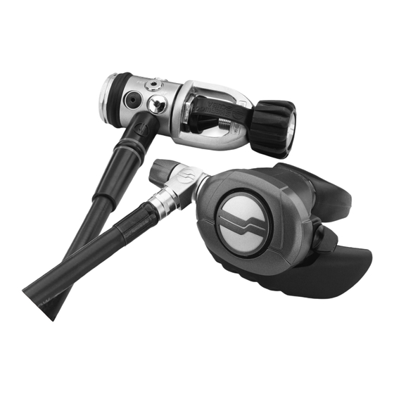
- Page 1 ® REGULATORS ® (SRB5600) Assembly & Maintenance Guide...
- Page 2 FIRST STAGE - MAXIMUS™ SRB5600 The model number of the regulator is laser stamped on the first stage between two of the outlet ports. ITEM # CATALOG # DESCRIPTION 1 ...5105-70 ..Handwheel 2 .
-
Page 3: Table Of Contents
Scheduled Maintenance ......24 BEFORE YOU BEGIN..READ THESE INSTRUCTIONS COMPLETELY BEFORE YOU BEGIN SERVICING THE REGULATOR. THESE INSTRUCTIONS ARE INTENDED FOR PEOPLE WHO HAVE BEEN AUTHORIZED BY SHERWOOD TO REPAIR SHERWOOD SCUBA EQUIPMENT. IF YOU ARE NOT SO AUTHORIZED - STOP. -
Page 4: Introduction
Sherwood or your Sherwood Sales Representative. NOTE: You must be authorized by Sherwood to work on Sherwood Scuba equipment. You can obtain proper authorization by attending all appropriate seminars given in your area. This is the only way you can... - Page 5 Companion instructional VHS videotapes to this and other Sherwood Scuba repair manuals are available from Sherwood Scuba at a nominal cost. Ask your Sherwood Scuba Sales Representative for details. If you have any questions, or need more information, contact your Sherwood Scuba Sales Representative.
-
Page 6: Specifications
2.0 SPECIFICATIONS SPECIFICATIONS FOR THE SRB5600 MAXIMUS REGULATOR MODEL: Sherwood SRB5600 Maximus AIR FLOW: 33 cu. ft. (935 liters)/min. @ 1 atmosphere INHALATION RESISTANCE: .9" - 1.5" (2.3 - 3.8 cm) w.c @ 1 atmosphere (adjustable) EXHALATION RESISTANCE: 0.7" (1.8 cm) w.c. max. @ 1 atm. RECOMMENDED LUBRICANT: Christo-Lube MCG111 (Sherwood p/n SW-MS150) -
Page 7: O-Rings Reference Chart
3.0 O-RINGS REFERENCE CHART Before you begin disassembly of the regulator, test the first and second stages for output pressures and leakage. Pre-testing in this way will help the technician to pinpoint any specific problems requiring repair. The work area must be clean and well lighted, with clean compressed air available to blow sand and dirt from parts. -
Page 8: First Stage Procedures
4.0 FIRST STAGE PROCEDURES TOOLS REQUIRED FOR FIRST STAGE SERVICING – Bench vise – 3/32" Allen wrench – 5/32" Allen wrench – 6" or 8" adjustable wrenches – 15" adjustable wrench – Phillips screwdriver – #10 Torx screwdriver – Sherwood 50 cc Graduated Cylinder (p/n TL110) –... - Page 9 Install a Sherwood regulator support handle (p/n TL113) into one of the low-pressure ports. Use the support handle and a 15" adjustable wrench or bench vise to loosen the yoke nut from the body . See Photo #1. Photo #1 Remove the yoke and yoke nut from the body.
- Page 10 Photo #2 Note: If no air is bubbling from the one-way bleed valve, this is a good indication that the positive air purge system is not working. Use a pocket screw driver to remove the black washer that was beneath the element assembly.
- Page 11 The sealing surface on the body where the one-way valve seals must be totally clean of deposits. If any deposits remain on the sealing surface after initial cleaning, take a fine abrasive polishing stick or and polish the surface to remove deposits (see Photo #3). Photo #3 Blow all residue from the body after polishing.
-
Page 12: Assembly Of First Stage
ASSEMBLY OF FIRST STAGE The part number for each regulator kit can be found in Sherwood’s Tools, Repair Kit and Accessories – Assembly & Maintenance Guide. The kits contain the parts that are always replaced at every annual service interval. The kit number for the Maximus is 4000-4. For Nitrox use, the kit # is 4000-4N. -
Page 13: Testing Of First Stage
Using the regulator support handle (p/n TL113) in one of the LP pressure ports of the body and a 15" adjustable wrench, tighten the yoke nut snugly (see Photo #1). Install the handwheel and the dust cap onto the yoke. If the first stage has a SAA-5300 DIN adapter installed instead of a standard yoke, see the installation instructions given in Sherwood Technical Bulletin #104 for overhaul and installation instructions of the DIN adapter. - Page 14 Intermediate Pressure Test NOTE: This test determines the regulator’s lock-up pressure (the pressure put out by the first stage during a no-flow condition). Attach any Sherwood second stage to one of the low pressure ports, and the Sherwood intermediate pressure gauge (p/n TL119) to another low pressure port. Plug all other ports with appropriate port plugs.
-
Page 15: Second Stage Procedures
5.0 SECOND STAGE PROCEDURES TOOLS REQUIRED FOR SECOND STAGE SERVICING – Two good quality 6" or 8" (15 or 20 cm) adjustable wrenches – #10 Torx screwdriver – Side cutting pliers – Sherwood Plastic Probe (p/n TL111) to push out orifice –... - Page 16 Using a small slotted screwdriver, remove the cir-clip from the adjusting orifice Use a 5/8" wrench to remove the retainer nut from the orifice housing . Hold the base of the orifice housing with a 3/4" wrench while doing this. Remove the swivel fitting from the orifice housing.
-
Page 17: Assembly Of Second Stage
NOTE: If only the lever is to be replaced, do not totally remove the screw. You can remove the lever from under the screw when the screw is almost all the way out. Hold the orifice housing in one hand. Temporarily install the adjuster knob and use it to turn the orifice clockwise until it comes out of the orifice housing. - Page 18 Screw the orifice housing onto the threads of the lever assembly. Using a 3/4" wrench on the orifice housing tighten them together snugly (70 in. lbs., 7.8nm). NOTE: A drop of mild thread locker, such as Locktite 242® or equivalent should be applied to the threads of the lever support to prevent the Orifice Housing from loosening during use.
-
Page 19: Set-Up Of Second Stage
Install the exhaust tee onto the case using the two screws NOTE: Depending on the owner’s needs, either the Blizzard, Oasis and Maximus style extended tee maximum bubble dispersion, or the Magnum/Brut style shorter tee for minimum weight and drag, can be installed on any of the three models. - Page 20 If the hissing has stopped properly, continue turning the knob clockwise until the stop is felt. Breathe on the regulator. It should breathe fairly hard at this setting, but still deliver a good air supply. Check the purge button for proper operation. After setting the poppet screw and orifice , the relationship between the diaphragm wear...
-
Page 21: Testing Of Second Stage
TESTING OF SECOND STAGE Inhalation Effort If you have no instrumentation, breathe on the regulator to test the breathing effort. With the adjusting knob turned fully counter-clockwise a slight hissing free flow should be heard. The hissing should stop when the knob is turned slightly clockwise. The breathing should be easy at this point. - Page 22 Intermediate Pressure Air Leaks Attach the regulator first stage to a tank short enough to totally submerge the first and second stage in your filling station cooling water. Adjust the breathing effort knob to the minimum breathing effort position (not the slight freeflow position). With the tank valve still turned off, flood the second stage completely with water, and then position it mouthpiece up.
-
Page 23: Helpful Hints
6.0 HELPFUL HINTS TROUBLESHOOTING REGULATORS POSSIBLE CAUSE RECOMMENDED ACTION A. High Inhalation Effort at Depth: 1. Inlet filter clogged. Replace the filter. 2. No air flowing through the dry air bleed system. Check the flow rate coming out of the one-way bleed valve . - Page 24 C. Wet Breathing: 1. Improper clearing, or diver diving in total Instruct the diver on proper clearing head-down position. technique. 2. Leaking past adjusting lever Install new o-ring . Check sealing surface & groove. 3. Diaphragm improperly installed or holed. Check position of diaphragm visually.
-
Page 25: Parts Cleaning Recommendations
PARTS CLEANING RECOMMENDATIONS Regulators which see heavy use, particularly those used in salt water, often require extra effort to remove dirt and corrosion from the parts of the regulator. Some suggested cleaning solutions are listed at the end of this section, and there are probably many others being used successfully. -
Page 26: Handling Tips
How your customers treat their regulators will directly influence the unit’s function and durability. Following are a few tips that you can pass on to your customers to help assure the durability of their Sherwood Scuba regulator. Pre-Dive Checks Check the hoses and hose connections for cuts, abrasions or other signs of damage before mounting the regulator on the tank valve. -
Page 27: Two Year Warranty And Maintenance Information
Part Five of the form. If this area is blank, you will not receive credit for that part. For Sherwood Scuba regulators manufactured before Jan. 1, 1993 which still have a valid Lifetime Limited Warranty, you, the dealer, must send the white Warranty Service Form to Sherwood. The information will be recorded by Sherwood to determine whether or not the warranty on that particular regulator is still in effect. - Page 28 SECOND STAGE REGULATOR - MAXIMUS™ SRB5600 NOTE: Labels (Item 1 below) in white, purple, pink, green, blue and yellow are available. ITEM # CATALOG # DESCRIPTION 1 ... G011B....O-ring (hose inlet end) 2 .
- Page 29 6204 Goodrich Road Clarence Ctr, New York 14032 www.sherwoodscuba.com Sherwood Scuba, the SS symbol, Oasis, Blizzard, Magnum, Brut and Wisdom are trademarks of Sherwood, Harsco Corporation Gas and Fluid Control Group. © 2001 The Liberty Group All other names are trademarks of their respective owners.
Need help?
Do you have a question about the maximus SRB5600 and is the answer not in the manual?
Questions and answers