Table of Contents
Advertisement
Quick Links
Rigel 6 QRG
Quick reference guides are not a replacement for the supplied instructions, they are
supplementary.
Read and understand the installer warnings in the main instruction document first.
Always apply good safe, state of the art engineering and electrical installation principles.
Safety of the completed installation is the ultimate responsibility of the installer.
This product is not suitable for DIY use and should only be installed and maintained by a
trained, skilled, professional installer.
Advertisement
Table of Contents

Related Manuals for BFT Rigel 6 QRG


Summary of Contents for BFT Rigel 6 QRG
- Page 1 Rigel 6 QRG Quick reference guides are not a replacement for the supplied instructions, they are supplementary. Read and understand the installer warnings in the main instruction document first. Always apply good safe, state of the art engineering and electrical installation principles.
-
Page 2: What's New
What's New Ø Multi coloured cable connections in line with current control panels. Ø Built in 7 day time clock. Ø 4 Chanel radio receiver. Ø Facility to remove individual transmitters. Ø Magnetic lock powered constantly during closing cycle. Ø U Link. Ø... -
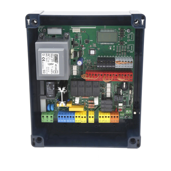
Page 3: Terminal Layout
Terminal Layout... - Page 4 Rigel 5 to Rigel 6 (terminal numbers)
-
Page 5: Motor Connections
Motor Connections Old Rigel 5 New Rigel 6 Motor 1, 10,11,12, opens first followed by Motor 2, 14,15,16, Motor 2 closes first followed by Motor 1 Capacitor is connected across motor winding M1=10 &12 M2=14 &16... - Page 6 Rigel 6 common connections Capacitor Capacitor Mag Lock or CISA Ic Inputs 1,2,3,4, 8K2 resistive, 70-72 or 70-74, Logic 8 75 & 76 SAFE 3 = 004 Photo cells, active closing only Desme...
-
Page 7: Menu System
Menu System X 2 Rapidly = Traditional Menu = Quick Menu To enter the traditional Menu press the OK button twice rapidly, Halt > OK > Follow user guide OK > Para >Logic>Radio>Default... - Page 8 Quick Menu Layout This will provide a working system...
- Page 9 Method (2 motor application) • Motor 1 opens first followed by motor 2, motor 2 closes first followed by motor • Capacitor is connected across 10 & 12 M1, 14 & 16 M2 • Single leaf applications use Motor 1 output 10,11,12. •...
- Page 10 Autoset from Program panel to Autoset and press OK, 3,2,1. motor 1 will open, when the open position is reached press the OK button 3.2.1. motor 2 will open, when the open position is reached press the OK button. With showing press the OK button 3.2.1, motor 2 will close, when the closed position is reached press the OK button 3.2.1.
-
Page 11: Time Clock
Time Clock Setting Clock for the day of the week Day of install i.e. Tuesday... - Page 12 Time Clock First ON ie 08.00 First OFF ie10.20 Second ON ie 15.00 Second OFF ie 16.10 First ON/OFF period Programming in 10 min blocks. Second ON/OFF period 1 = 10 past the hour 2 = 20 past 3 = 30 past 4 = 40 past 5 = 50 past Example...
- Page 13 Radio Individual transmitters can be removed from any channel. The location number within the radio channel must be known to carry out this function...
- Page 14 Radio Programming Example’s How to hold a pair gates open with Second button on a Mitto 2-4. Code the Second button on a Mitto into the 2 radio channel, Program: Ic1 = 5 (60-61), Aux Out 2 =14 (24-25), 2ch =8 Wire between 24&61, 25&60.
- Page 15 Obstacle Sensitivity...
Need help?
Do you have a question about the Rigel 6 QRG and is the answer not in the manual?
Questions and answers