
Related Manuals for KAP MR-LVT-170925


Summary of Contents for KAP MR-LVT-170925
- Page 1 LEVANTE 2017year QUATTROPORTE 2017year GHIBLI 2017year (VIDEO Interface) MODEL MR-LVT-170925 DATE 2017.11.20...
- Page 2 Main Spec. 1. Input Spec. (MULTI VIDEO INTERFACE) - 1 x Analog RGB Input (Navigation System source) - 1 x Digital RGB Input (Navigation System source) - 1 x CVBS(REAR CAMERA) Input. (Rear camera source) - 1 x CVBS(FRONT CAMERA) Input. (Front camera source) 2.
-
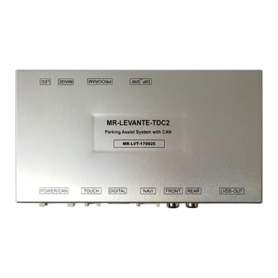
Page 3: External Appearance
External Appearance PROGRAM IMAGE DIP S/W LCD-OUT POWER/CAN Digital Video Analog Rear R-TOUCH Camera... -
Page 4: Connector Pin Assignment
Connector Pin Assignment *POWER Connect *Touch Connect *NAVI Connect ① ② ③ ④ ① ② ③ ④ ⑤ ⑥ ⑦ ① Y- ① R DATA (Red) 1. Battery (Yellow) 9. CAN-L (Green) ② X- ② G DATA (Green) 2. Battery (Yellow) 10. -
Page 5: Product Composition
Product Composition 60*100*0.5*P6 opposite direction 30*100*1.0*P7 right direction Touch IN/OUT 4-pin Cable(180mm) 1 EA LVDS FFC Cable 2 EA Interface 1 EA FD-PAS-170327 Power Cable 1 EA LVDS Cable(800mm) 1 EA LVDS extension Board 1 EA SUB Board (R01) 1 EA RGB NAVI Cable 1 EA OSD Board 1 EA... -
Page 6: Dip S/W Setting
DIP S/W Setting * ON : DOWN , OFF : UP * DIP S/W Example FUNCTION DIP S/W Selection LEVANTE(2017) 8” QUATTROPORTE(2017) 8” ON : Not Used NAVI GHIBLI(2017) 8” OFF : Used ON : Not Used AV1 (DVB-T) OFF : Used ON : Not Used AV2 (DVD) OFF : Used... -
Page 7: Mode Change
Mode Change Press long : switching mode Press Short : switching to OEM directly ※The screen is switched in order as the pictures below NAVI... - Page 8 Mode Change * Steering Wheel Button Control • Use Steering button, Enter OSD menu, and select “ON” If not use, select “OFF” Push long – Mode Change ※The screen is switched in order as the pictures below NAVI...
-
Page 9: Touch Control
Touch Control Touch calibration Push 7sec on the NAVI / AV1 / AV2 screen ( just 1 screen) Press+... - Page 10 Touch Control DVB-T/DVD Control DVB-T Press Touch(Anywhere) Press Icon...
-
Page 11: Osd(On Screen Display) Control
OSD(On Screen Display) Control OSD Control Board MENU DOWN MENU Push -> OSD menu On/Off Item Selection, Value Selection Item up Increase selected value DOWN Item down Decrease selected value Mode State First Menu Second Menu Third Menu... - Page 12 OSD(On Screen Display) Control First Menu Second Menu Third Menu Action Original Camera RearCam-Type ExtDevice Use aftermarket Rear camera Rear camera get +12V consistently RearCam-Power AUTO Rear camera get +12V when reverse gear on Shut out the power supply. Original Camera FrontCam-Type Option ExtDevice...
- Page 13 OSD(On Screen Display) Control NAVI-RGB menu DVD,DVB-T(DMB),NAVI-AV,REAR,FRONT menu First Menu Second Menu Third Menu Action First Menu Second Menu Third Menu Action Brightness Adjust the value of brightness Brightness Adjust the value of brightness Contrast Adjust the value of contrast Contrast Adjust the value of contrast Color-RED...
- Page 14 OSD(On Screen Display) Control OSD Setting– Screen Mode - Horizontal - Vertical - Scaler X Up - Scaler X Down - Scaler Y Up - Scaler Y Down...
- Page 15 OSD(On Screen Display) Control OSD Setting – Parking Mode On/Off Parking Line ON Parking line OFF On Reverse mode enter this OSD menu...
- Page 16 OSD(On Screen Display) Control OSD Setting – Warnings Language Change...
- Page 17 OSD(On Screen Display) Control OSD Setting – Front Camera Auto Mode - Option -> RearCam-RcvOpt -> 0 second = RearCam-RcvOpt menu OFF 1~30 second = RearCam-RcvOpt menu ON & time control NAVI NAVI REAR FRONT AV1(DVB-T) AV1(DVB-T) AV2(DVD) AV2(DVD) 1~30 second...
- Page 18 OSD(On Screen Display) Control OSD Setting – Utility Mode - Factory Reset : Execute - Reset All (Setting Default) - Version : FW Version Finish update FW, check the FW versoin Last Source : BEPP06SGX-130950 Software Version Software Month Software Year Special Version National : CN=CHINA, KR=KOREA, JP=JAPAN, US=United States Hardware Version...
- Page 19 Install Manual 1. Installation Navigation Connection *KD-900 navigation DVD-IR DVBT-IR SYNC Analog RGB BLUE GREEN Resistive Touch 16. GND (Black) 15. GND (Black) 14. Mode (Green) 13. Front-Power (Red) 12. Rear-Power (Red) 11. ACC (Red) KD-900 10. N.C 9. N.C 8.
- Page 20 Install Manual 2. Installation DVB-T Remote Control Connection ① or ② 선택1 ① DVBT-IR DVD-IR DVBT-IR SYNC BLUE GREEN GEX-909DTV 16. GND (Black) 15. GND (Black) 14. Mode (Green) 13. Front-Power (Red) ② 선택2 12. Rear-Power (Red) 11. ACC (Red) 10.
- Page 21 Install Manual 3. Installation DVD Remote Control Connection DVD-IR DVD-IR DVBT-IR SYNC BLUE GREEN 16. GND (Black) 15. GND (Black) 14. Mode (Green) 13. Front-Power (Red) 12. Rear-Power (Red) 11. ACC (Red) DHA-S690 10. N.C 9. N.C 8. CAN-H (Purple) GND (Black) 7.
- Page 22 Install Manual 4. Installation External Front Camera Connection FRONT-POWER (Red) GND (Black) 16. GND (Black) 15. GND (Black) 14. Mode (Green) 13. Front-Power (Red) 12. Rear-Power (Red) 11. ACC (Red) 10. N.C 9. N.C 8. CAN-H (Purple) 7. CAN-L (White) 6.
- Page 23 Install Manual 5. Installation External Reverse(Rear) Camera Connection REAR-POWER (Red) 16. GND (Black) 15. GND (Black) 14. Mode (Green) 13. Front-Power (Red) 12. Rear-Power (Red) 11. ACC (Red) 10. N.C +12V 9. N.C 8. CAN-H (Purple) 7. CAN-L (White) 6. CAN-H (Orange) 5.
- Page 24 Install Manual (Use Navigation) 6. Levante Touch in/out cable connection – When use AV or Rear CAM, DO NOT WORK THIS Before work Take out (0 ohm) resistor Soldering our cable to here...
- Page 25 Install Manual (Use Navigation) 7. Quattroporte Touch in/out cable connection – When use AV or Rear CAM, DO NOT WORK THIS Before work Soldering our cable to here Take out (0 ohm) resistor...
- Page 26 Install Manual 8. LVDS FPC cable connection Connect Our FFC Cable Connect Our FFC Cable Connect original FPC Cable Check the blue color on the cable...
- Page 27 Q & A 1. If Interface has a problem, Please check LED. - ACC on (12v), If Interface does not have a problem; GREEN LED is blinking every 1 sec.. LED is turn on (not blinking), Interface has a problem. LED is turn off every 1 sec, there is no input.
Need help?
Do you have a question about the MR-LVT-170925 and is the answer not in the manual?
Questions and answers