Table of Contents
Advertisement
Available languages
Available languages
Quick Links
READ AND SAVE THESE INSTRUCTIONS
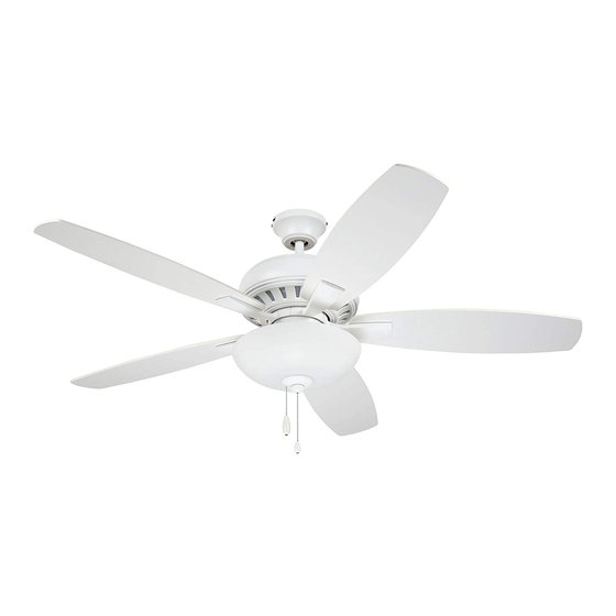
DC BUILDER ES Series
52" Ceiling Fan Owner's Manual
CF835AP00
CF835BS00
CF835ORB00
CF835SW00
Questions, problems, missing parts: Before returning to the store call
Part No. F40BP75750000
Revision: 191218
Model Numbers
- Antique Pewter
- Brushed Steel
- Satin White
Net Weight:
Customer Service - 8 a.m. - 6 p.m., Eastern, Monday-Friday
1-800-654-3545
www.emersonfans.com
- Oil Rubbed Bronze
15.7
Lbs.
• Español - página 29
Form No. BP7575
ETL Model No.: CF835
Advertisement
Table of Contents

Related Manuals for Emerson DC BUILDER ES Series


Summary of Contents for Emerson DC BUILDER ES Series
- Page 1 READ AND SAVE THESE INSTRUCTIONS DC BUILDER ES Series 52” Ceiling Fan Owner’s Manual Model Numbers CF835AP00 - Antique Pewter CF835BS00 - Brushed Steel CF835ORB00 - Oil Rubbed Bronze CF835SW00 - Satin White 15.7 Net Weight: Lbs. Questions, problems, missing parts: Before returning to the store call Customer Service - 8 a.m.
-
Page 2: Table Of Contents
Substitution of parts or accessories not designated Electrical Codes. Use the National Electrical Code for use with this product by Emerson could result in if Local Codes do not exist. The ceiling fan must be personal injury or property damage. -
Page 3: Unpacking Instructions
Substitution of parts or accessories not designated Flange Set for use with this product by Emerson could result in personal injury or property damage. Blade Set Open carton containing fan. Remove top half of styrofoam unit. -
Page 4: Electrical Requirements
1. Unpacking Instructions (Continued) This Manual Is Designed to Make it as Easy as Possible for You to Assemble, Install, Operate and Maintain Your Ceiling Fan Tools Needed for Assembly WARNING One Phillips Head Screwdriver One Stepladder Before assembling your ceiling fan, refer to section One 1/4”... -
Page 5: Removal Of The Hanger Bracket
IMPORTANT Your ceiling fan is designed to be installed either in the standard manner, or in the close-to-the-ceiling manner. Using the standard method, the hanger ball/downrod assembly will suspend the fan several inches below the ceiling cover. Using the close-to-the-ceiling method, the ceiling cover installs directly on the fan motor housing, thus mounting the fan 3-1/2 inches closer to the ceiling than the standard method. -
Page 6: Installing The Hanger Ball/Downrod Assembly (Standard)
4. Installing the Hanger Ball/Downrod Assembly (For Standard Mounting) Pass the 80” Motor Wires through the opening in the THREE 80" MOTOR WIRES Ceiling Cover. Be sure the Cover is oriented correctly (Figure 2). CEILING COVER Figure 2 THREE 80" Separate, untwist and unkink the Three Motor Wires. - Page 7 4. Installing the Hanger Ball/Downrod Assembly (For Standard Mounting) (Continued) DOWNROD HAIRPIN Loosen the Two Setscrews in the Motor Coupler. CLIP CLEVIS Place the Hanger Ball / Downrod Assembly into the Motor Coupler, aligning the Clevis Pin Holes in the Downrod with the Holes in the Motor Coupler (Figure 4).
-
Page 8: Installing The Ceiling Cover On The Fan Motor Housing (Close-To-Ceiling)
5. Installing the Ceiling Cover on the Fan Motor Housing (For Close-to-the-Ceiling Mounting) TOP VIEW Remove Three Motor Housing Screws (every other one) from the top of the Motor Housing (Figure 6). Retain the Three Motor Housing Screws for future use. REMOVE SCREWS (3) REMOVE 3 MOTOR... - Page 9 5. Installing the Ceiling Cover on the Fan Motor Housing (For Close-to-the-Ceiling Mounting) (Continued) REINSTALL THREE SCREWS MOTOR (Previously Removed) Align the Holes in the Ceiling Cover with the Holes in HOUSING the Motor Housing. CEILING COVER Reinstall the Three Screws previously removed and tighten to secure the Ceiling Cover to the Motor Housing (Figure 9).
-
Page 10: How To Hang Your Ceiling Fan
6. How to Hang Your Ceiling Fan CAUTION CEILING To reduce the risk of injury, install the fan so that the blades are at least 7 ft. (2.1m) above the floor (Figure 11). WARNING The outlet box and joist must be securely mounted and capable of supporting at least 50 lbs. -
Page 11: Hanging The Ceiling Fan (Standard)
6. How to Hang Your Ceiling Fan (Continued) NOTE: The hanger bracket must be mounted flush with the ceiling in order for the ceiling cover to install properly. If necessary, use leveling washers (not supplied) between the outlet box and the hanger bracket. -
Page 12: Hanging The Ceiling Fan (Close-To-Ceiling)
8. Hanging the Ceiling Fan (Close-to-the-Ceiling Method with Ceiling Cover Installed on the Motor Housing) Carefully lift the Fan Assembly up to the Hanger Bracket. Pass the Hook on the Hanger Bracket through One of the Screw Holes (NOT the slots) in the Ceiling Cover (Figure 15). -
Page 13: How To Wire Your Ceiling Fan
9. How to Wire Your Ceiling Fan The following instructions show that the Hanger Ball/Downrod Assembly and the Close-To-The-Ceiling Assembly wiring instructions are the same. HANGER BALL/DOWNROD ASSEMBLY SHOWN If you feel that you do not have enough electrical wiring knowledge or experience, have your fan GROUND installed by a licensed electrician. - Page 14 9. How to Wire Your Ceiling Fan (Continued) HANGER BALL/DOWNROD ASSEMBLY SHOWN Securely connect the Fan Motor Black Wire and Blue Wire to the Supply Black (Hot) Wire using Wire LISTED WIRE Connector Supplied (Figure 18). CONNECTOR SUPPLY BLACK (HOT) BLUE FAN WIRE FAN MOTOR...
-
Page 15: Installing The Ceiling Cover
10. Installing the Ceiling Cover 10.1 HANGER BALL/DOWNROD ASSEMBLY SHOWN Remove the Left Screw and Lockwasher from each side of the Hanger Bracket (Figure 20) and loosen the other Two Screws. NOTE: When installing the ceiling fan using the REMOVE LEFT close-to-the-ceiling method, carefully lift the fan SCREW AND assembly from the hook on the hanger bracket and... -
Page 16: Installing The Fan Blades
11. Installing the Fan Blades 11.1 #10 - 24 x 7 mm WASHER HEAD SCREWS (3 per blade) WARNING To reduce the risk of personal injury, do not bend the blade flanges when installing the flanges, balancing FAN BLADE the blades, or cleaning the fan. Do not insert foreign objects between rotating fan blades. -
Page 17: Installing The Light Fitter & Shade
12. Installing the Light Fitter and Shade 12.1 SWITCH HOUSING CAUTION To reduce the risk of electric shock, disconnect the electrical supply circuit to the fan before installing light kit. WIRE CONNECTORS (2) Remove and Retain the Two Wire Connectors in the Switch Housing (Figure 25). - Page 18 12. Installing the Light Fitter and Shade (Continued) 12.3 Connect the Ceiling Fan Blue Wire to the Light Fitter SWITCH HOUSING Black Wire. Use one of the Wire Connector (previously removed) to make the connection (Figure 27). SWITCH HOUSING BLUE WIRE LIGHT FITTER BLACK WIRE WIRE...
- Page 19 12. Installing the Light Fitter and Shade (Continued) 12.5 Install Three 9-Watt Medium Base LED Bulbs (supplied) into the Light Fitter Sockets (Figure 29). WARNING To avoid possible fire hazard, do not exceed wattage indicated on the fitter. LIGHT FITTER SOCKETS (3) 9-WATT MEDIUM BASE...
- Page 20 12. Installing the Light Fitter and Shade (Continued) 12.7 Position the Shade over the Threaded Nipple and seat Bowl on Bowl Cap (Figure 31). Pass the Fan Pull Chain through the Bushing in the Outer Bowl Cap and install the Cap on the Threaded Nipple.
-
Page 21: Using Your Ceiling Fan
13. Using Your Ceiling Fan 13.1 Restore Electrical Power to the Outlet Box by turning REVERSE SWITCH the Electricity on at the Main Fuse Box. SWITCH During Summer Months, run the Fan Counter- HOUSING Clockwise, as you look up at it, to direct airflow downward. -
Page 22: No Light Installation
14.3 REVERSE SWITCH Remove and Retain the Three #8-32 x 8 mm Flat Head LONG SLOT SWITCH Screws from the Switch Housing (Figure 37). HOUSING Be sure all Wires are inside the Switch Housing. WARNING PULL CHAIN CURVED SLOT To avoid fire or electrical shock, be careful not to pinch wires between the switch housing assembly and the cover. -
Page 23: Maintenance
Abrasive cleaning agents are not required and should be avoided to prevent damage to finish. See your local Emerson dealer, www.emersonfans.com or the Emerson Ceiling Fan Catalog for these Accessories: • Downrod Extension Kits emersonfans.com Please contact 1-800-654-3545 for further assistance... -
Page 24: Repair Parts
18. Repair Parts PARTS BAG ETL Model No.: CF835... - Page 25 18. Repair Parts Listing Part Numbers Model Number Model Number Model Number Model Number Description CF835AP0 CF835BS0 CF835ORB0 CF835SW0 Hanger Pack Assembly, Consisting of: 762231-10 762231-4 762231-8 762231-9 Hanger Bracket (1) — — — — Hanger Ball/Downrod Assembly (1) — —...
-
Page 26: Troubleshooting
19. Troubleshooting WARNING FOR YOUR OWN SAFETY TURN OFF POWER AT FUSE BOX OR CIRCUIT BREAKER BEFORE TROUBLESHOOTING YOUR FAN. TROUBLE PROBABLE CAUSE SUGGESTED REMEDY 1. Fan will not start. 1. Fuse or circuit breaker blown. 1. Check main and branch circuit fuses or circuit breakers. -
Page 27: Ceiling Fan Limited Warranty
What We Will Do To Correct Problems: If the defect is covered by this limited warranty, Emerson will repair or replace the applicable Emerson Ceiling Fan Product at no charge to You. If repair of the Emerson Ceiling Fan Product is not practical or possible within a reasonable time and no replacement Emerson Ceiling Fan Product can be provided, Emerson will refund You the actual purchase price of Your Emerson Ceiling Fan Product. - Page 28 DATE CODE: The date code of this fan may be found on the box, stamped in ink on a white label. You should record this data above and keep it in a safe place for future use. DIVISION OF LUMINANCE BRANDS 1945 S.
-
Page 29: Spanish
LEA Y GUARDE ESTAS INSTRUCCIONES Serie DC BUILDER ES Manual del usuario para ventiladores de techo de 52 pulgadas Números de modelo CF835AP00 – Estaño antiguo CF835BS00 – Acero cepillado CF835ORB00 – Bronce aceitado CF835SW00 – Blanco satén 15,7 Peso neto: Preguntas, problemas, piezas faltantes: Antes de devolver el producto a la tienda, llame al Servicio al Cliente 8 a.m. - Page 30 La sustitución Locales. Utilice el Código Eléctrico Nacional si no existen Códigos con piezas o accesorios no diseñados por Emerson para utilizarse Locales. El ventilador de techo se debe conectar a tierra como con este producto podría causar lesiones corporales o daños precaución contra posibles descargas eléctricas.
- Page 31 4,5 pulg. diseñados específicamente para utilizarse con este producto. La Bombillas LED de base mediana de 9 W sustitución con piezas o accesorios no diseñados por Emerson para utilizarse con este producto podría causar lesiones Conjunto de pestañas corporales o daños materiales.
- Page 32 1. Instrucciones de desempaquetado (continuación) Este manual está diseñado para que usted pueda ensamblar, instalar, utilizar y mantener su ventilador de techo de la manera más fácil posible Herramientas necesarias ADVERTENCIA para el ensamblaje Antes de ensamblar su ventilador de techo, consulte la sección Un destornillador de cabeza Phillips Una escalera de mano sobre el método apropiado para cablear el ventilador (página...
- Page 33 IMPORTANTE Su ventilador de techo está diseñado para instalarse de la manera estándar o de la manera cerca del techo. Al utilizar el método estándar, el ensamblaje de esfera de suspensión/varilla descendente suspenderá el ventilador varias pulgadas por debajo de la cubierta del techo. Al utilizar el método cerca del techo, la cubierta del techo se instala directamente sobre la carcasa del motor del ventilador, con lo cual el ventilador se monta 3-1/2 pulgadas más cerca del techo que en el método estándar.
- Page 34 4. Instalación del ensamblaje de esfera de suspensión/ varilla descendente (para realizar el montaje estándar) Pase los cables de conexión del motor de 80 pulgadas a través TRES CABLES DE CONEXIÓN DEL de la abertura ubicada en la cubierta del techo. MOTOR DE 80 PULG.
- Page 35 4. Instalación del ensamblaje de esfera de suspensión/ varilla descendente (para realizar el montaje estándar) (continuación) VARILLA DESCENDENTE CLIP DE Afloje los dos tornillos de ajuste ubicados en el acoplamiento HORQUILLA del motor. PASADOR DE HORQUILLA Coloque el ensamblaje de esfera de suspensión/varilla descen dente PASADOR en el interior del acoplamiento del motor, alineando los agujeros DE HORQUILLA...
- Page 36 5. Instalación de la cubierta del techo sobre la carcasa del motor del ventilador (para realizar el montaje cerca del techo) VISTA SUPERIOR Retire tres tornillos de la carcasa del motor (uno de cada dos tornillos de la parte superior de la carcasa del motor (Figura 6). Retire los tres tornillos de la carcasa del motor para uso futuro.
- Page 37 5. Instalación de la cubierta del techo sobre la carcasa del motor del ventilador (para realizar el montaje cerca del techo) (cont.) REINSTALE LOS TRES TORNILLOS CARCASA (retirados previamente) DEL MOTOR Alinee los agujeros de la cubierta del techo con los agujeros de la CUBIERTA carcasa del motor.
- Page 38 6. Cómo colgar su ventilador de techo PRECAUCIÓN TECHO Para reducir el riesgo de lesiones, instale el ventilador de manera que las paletas estén al menos a 7 pies (2.1 m) de altura sobre el piso (Figura 11). ADVERTENCIA La caja de tomacorriente y la viga deben estar montadas de POR LO manera segura y ser capaces de soportar por lo menos 50 lb.
- Page 39 6. Cómo colgar su ventilador de techo (continuación) NOTA: El soporte de suspensión se debe montar al ras con el techo para que la cubierta del techo se instale correctamente. Si es necesario, utilice arandelas niveladoras (no sumi- nistradas) entre la caja de tomacorriente y el soporte de suspensión.
- Page 40 8. Suspensión del ventilador de techo (método cerca del techo con la cubierta del techo instalada sobre la carcasa del motor) Levante cuidadosamente el ensamblaje del ventilador hasta el soporte de suspensión. Pase el gancho ubicado en el soporte de suspensión a través de uno de los agujeros para tornillo (NO lo pase a través de las ranuras) ubicados en la cubierta del techo (Figura 15).
- Page 41 9. Cómo cablear su ventilador de techo Las siguientes instrucciones muestran que las instrucciones de cableado son las mismas para el ensamblaje de esfera de suspensión/varilla descendente y para el ensamblaje cerca del techo. SE MUESTRA EL ENSAMBLAJE DE ESFERA DE SUSPENSIÓN/VARILLA DESCENDENTE Si le parece que no tiene suficientes conocimientos o CABLE DE...
- Page 42 9. Cómo colgar su ventilador de techo (continuación) SE MUESTRA EL ENSAMBLAJE DE ESFERA Conecte de manera segura el cable negro del motor y el cable DE SUSPENSIÓN/VARILLA DESCENDENTE azul del ventilador al cable negro de suministro (con corriente) CONECTOR DE utilizando el conector de cables suministrado (Figura 18).
- Page 43 10. Instalación de la cubierta del techo 10.1 SE MUESTRA EL ENSAMBLAJE DE ESFERA DE SUSPENSIÓN/VARILLA DESCENDENTE Retire el tornillo y la arandela de seguridad de la parte izquierda de cada lado del soporte de suspensión (Figura 20) y afloje los otros dos tornillos.
- Page 44 11. Instalación de las paletas del ventilador 11.1 TORNILLOS CON CABEZA DE ARANDELA #10 - 24 x 7 mm (3 por paleta) ADVERTENCIA Para reducir el riesgo de lesiones corporales, no doble las pestañas de la paleta cuando instale dichas pestañas, equilibre PALETA DEL VENTILADOR las paletas o limpie el ventilador.
- Page 45 12. Instalación del ajustador de la luz y la pantalla 12.1 CARCASA DEL PRECAUCIÓN INTERRUPTOR Para reducir el riesgo de descargas eléctricas, desconecte el circuito de alimentación eléctrica al ventilador antes de instalar el kit de iluminación. CONECTORES DE CABLES (3) Retire y retenga los dos conectores de cables ubicados en la carcasa del interruptor (Figura 25).
- Page 46 12. Instalación del ajustador de la luz y la pantalla (continuación) 12.3 Conecte el cable azul del ventilador de techo al cable negro CARCASA DEL del ajustador de la luz. Use el conector de cables (retirado INTERRUPTOR previamente) para hacer la conexión (Figura 27). CABLE AZUL DE LA CARCASA DEL INTERRUPTOR...
- Page 47 12. Instalación del ajustador de la luz y la pantalla (continuación) 12.5 Instale tres bombillas LED de base mediana de 9 W (suministradas) en los portalámparas del ajustador de la luz (Figura 29). ADVERTENCIA Para evitar un posible peligro de incendio, no exceda el vatiaje indicado en el ajustador de la luz.
- Page 48 12. Instalación del ajustador de la luz y la pantalla (continuación) 12.7 Posicione la pantalla sobre el niple roscado y asiente el globo sobre la tapa del globo (Figura 31). Pase la cadena de tiro del ventilador a través del casquillo ubicado en la tapa exterior del globo e instale la tapa sobre el niple roscado.
- Page 49 13. Utilización del ventilador de techo 13.1 Restablezca el suministro eléctrico a la caja de tomacorriente INTERRUPTOR DE INVERSIÓN encendiendo la electricidad en la caja de fusibles principal. Durante los meses de verano, utilice el ventilador de manera que CARCASA DEL INTERRUPTOR rote en sentido contrario al de las agujas del reloj, según se mira hacia arriba al ventilador, para dirigir hacia abajo la circulación...
- Page 50 14. Instalación sin luz 14.3 RANURA LARGA PARA Retire y retenga los tres tornillos de cabeza plana #8-32 x 8 mm EL INTERRUPTOR DE INVERSIÓN CARCASA DEL de la carcasa del interruptor (Figura 37). INTERRUPTOR Asegúrese de que todos los cables estén dentro de la carcasa del interruptor.
- Page 51 8 a 9 pies por encima del piso para lograr una produce una suave corriente ascendente, que fuerza el aire circulación de aire óptima. Consulte a su minorista Emerson para caliente que está cerca del techo a bajar al espacio ocupado.
- Page 52 PARTS BAG BOLSA DE PIEZAS No. de modelo ETL: CF835...
- Page 53 18. Piezas de repuesto Números de pieza No. de No. de modelo No. de modelo No. de modelo No. de modelo Descripción CF835AP0 CF835BS0 CF835ORB0 CF835SW0 clave Ensamblaje del paquete de suspensión, 762231-10 762231-4 762231-8 762231-9 que consiste en: Soporte de suspension (1) —...
- Page 54 13. Resolución de problemas ADVERTENCIA PARA SU PROPIA SEGURIDAD, DESCONECTE LA ALIMENTACIÓN ELÉCTRICA EN LA CAJA DE FUSIBLES O EL CORTACIRCUITO ANTES DE RESOLVER PROBLEMAS EN SU VENTILADOR. PROBLEMA CAUSA PROBABLE REMEDIO SUGERIDO 1. El ventilador no arranca. 1. Fusible o cortacircuito fundido. 1.
- Page 55 Para que Nosotros confirmemos que Su Producto de Ventilador de Techo Emerson sigue estando bajo garantía, sírvase retener Su recibo u otro comprobante de compra y tener esa información al alcance de la mano cuando envíe su Producto de Ventilador de Techo Emerson a Su lugar de compra o cuando llame a Servicio al Cliente de Emerson.
- Page 56 CÓDIGO DE FECHA: ____________________________________________________________________________________ El código de fecha de este ventilador se puede encontrar en la caja, estampado en tinta en una etiqueta blanca. Usted deberá anotar esta fecha arriba y guardarla en un lugar seguro para uso futuro. DIVISIÓN DE LUMINANCE BRANDS 1945 S.
Need help?
Do you have a question about the DC BUILDER ES Series and is the answer not in the manual?
Questions and answers