Grundfos MAGNA1 Installation And Operating Instructions Manual
Hide thumbs
Also See for MAGNA1:
- Instructions manual (316 pages) ,
- Installation and operating instructions manual (31 pages) ,
- Service kit instructions (22 pages)
Table of Contents
Advertisement
Quick Links
Advertisement
Table of Contents

Related Manuals for Grundfos MAGNA1


Summary of Contents for Grundfos MAGNA1
- Page 1 GRUNDFOS INSTRUCTIONS MAGNA1 Installation and operating instructions...
-
Page 2: Table Of Contents
Original installation and operating instructions 1. General information 1.1 Symbols used in this document CONTENTS These installation and operating instructions describe MAGNA1. DANGER Sections 1-5 give the information necessary to be able to unpack, Indicates a hazardous situation which, if not avoided, install and start up the product in a safe way. -
Page 3: Receiving The Product
Remove the tape before installing the Terminal-connected single-head pump Fig. 3 pump. The box contains the following items: 2.2 Scope of delivery • MAGNA1-pump 2.2.1 Plug-connected single-head pump • insulating shells • gaskets • quick guide •... -
Page 4: Lifting The Pump
2.3 Lifting the pump 3. Installing the product Observe local regulations concerning limits for manual lifting or handling. Always lift directly on the pump head or the cooling fins when handling the pump. See fig. 5. 3.1 Location For large pumps, it may be necessary to use lifting equipment. The pump is designed for indoor installation. -
Page 5: Mechanical Installation
The liquid flow To ensure adequate cooling, make sure that the control box is in direction can be horizontal or horizontal position with the Grundfos logo in vertical position. See vertical, depending on the fig. 9. control-box position. - Page 6 3.3.3 Pump head position If you remove the pump head before installing the pump in the pipes, pay special attention when fitting the pump head to the pump housing: 1. Visually check that the floating ring in the sealing system is centred.
- Page 7 Place the control box in horizontal position so that the As an alternative to insulating shells, you can insulate the pump Grundfos logo is in vertical housing and pipes as illustrated in fig. 13. position. The motor shaft must be in horizontal position.
-
Page 8: Electrical Installation
3.4 Electrical installation Step Action Illustration Connect the cable gland to the Carry out the electrical connection and protection according to control box. local regulations. Check that the supply voltage and frequency correspond to the values stated on the nameplate. WARNING Electric shock Death or serious personal injury... - Page 9 Plug-connected versions Step Action Illustration Assembling the plug Step Action Illustration Max. 1.5 mm Fit the cable gland and plug cover to Insert the power 12 mm the cable. Strip supply plug into the cable Ø 5.5 - 10 mm the male plug in conductors as the control box.
- Page 10 3.4.3 Connection diagrams External switch Fuse RCD/RCCB Fig. 15 Example of a mains-connected motor with main switch, backup fuse and additional protection External switch Fuse RCD/RCCB Fig. 16 Example of a plug-connected motor with main switch, backup fuse and additional protection Make sure that the fuse is dimensioned according to the nameplate and local regulations.
-
Page 11: Starting Up The Product
4. Starting up the product The number of starts and stops via the power supply must not exceed four times per hour. Do not start the pump until the system has been filled with liquid and vented. Furthermore, the required minimum inlet pressure must be available at the pump inlet. -
Page 12: Product Introduction
Maximum viscosity: 50 cSt ~ 50 % water / 50 % glycol mixture at -10 °C. The pump has a power-limiting function that protects it against Grundfos MAGNA1 is a complete range of circulator pumps with overload. integrated controller enabling adjustment of pump performance to The pumping of glycol mixtures affects the maximum curve and the actual system requirements. -
Page 13: Identification
6.3 Identification 6.4 Insulating shells Insulating shells are available for single-head pumps only. 6.3.1 Nameplate Limit the heat loss from the pump housing and pipes. Reduce the heat loss from the pump and pipes by insulating the pump housing and the pipes. See fig. 20. •... -
Page 14: Control Functions
7. Control functions Constant-pressure curve (CP1, CP2 or CP3) Constant-pressure control adjusts the pump performance to the actual heat demand in the system, but the pump performance follows the selected performance curve, CP1, CP2 or CP3. See fig. where CP1 has been selected. For further information, see section 8. -
Page 15: Overview Of Control Functions
7.1 Overview of control functions Fig. 26 Pump setting in relation to pump performance Setting Pump curve Function The duty point of the pump will move up or down on the lowest proportional-pressure curve, Lowest proportional-pressure depending on the heat demand. See fig. 26. curve The head is reduced at falling heat demand and increased at rising heat demand. -
Page 16: Selecting Control Function
7.2 Selecting control function System application Select this control mode In systems with relatively large pressure losses in the distribution pipes and in air-conditioning and cooling systems. • Two-pipe heating systems with thermostatic valves and the following: – very long distribution pipes Proportional pressure –... -
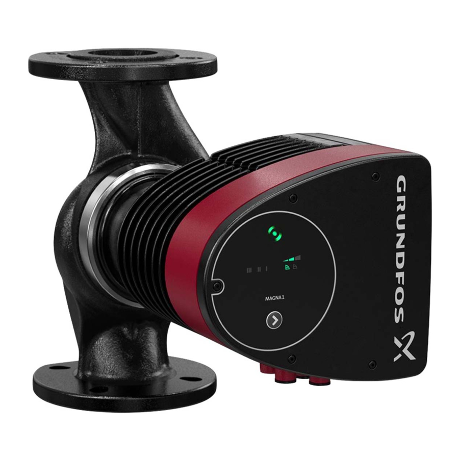
Page 17: Operating The Product
Push-button for selection of pump setting. referred to as CP3 7.4 Grundfos Eye Grundfos Eye is on when you switch on the power supply. See Constant curve III fig. 27, pos. 1. Grundfos Eye is an indicator light providing information about the actual pump status. -
Page 18: Fault Finding The Product
If not, replace the pump, or contact contains too much air. Grundfos Service. Fault in the pump electronics. Replace the pump, or contact Grundfos Service. The supply voltage to the pump is too high. Check that the power supply is within the specified range. -
Page 19: Accessories
ALPHA plug, angled, with 4 m cable 96884669 MAGNA1 32-40/60/80/100 (N) 98538853 ALPHA plug, angled, with inrush 97844632 protection with 1 m cable MAGNA1 32-40/60/80/100 F (N) 98538854 MAGNA1 32-120 F (N) 98164595 MAGNA1 40-40/60 F (N) 98538855 MAGNA1 40-80/100 F (N) -
Page 20: Technical Data
Minimum inlet pressure recycling of materials. The following average disposal values The following relative minimum inlet pressure must be available apply to all variants of MAGNA1 pumps: at the pump inlet during operation to avoid cavitation noise and • 85 % recycling damage to the pump bearings. - Page 21 Appendix 1. Dimensions Single-head pump dimensions, threaded version Fig. 1 Dimensions [mm] [inch] Pump type MAGNA1 25-40 (N) 1 1/2 MAGNA1 25-60 (N) 1 1/2 MAGNA1 25-80 (N) 1 1/2 MAGNA1 25-100 (N) 1 1/2 MAGNA1 25-120 (N) 1 1/2...
- Page 22 2. Dimensions Single-head pump dimensions, plug-connected versions, flanged version Fig. 3 Dimensions [mm] Pump type MAGNA1 32-40 F (N) 90/100 14/19 MAGNA1 32-60 F (N) 90/100 14/19 MAGNA1 32-80 F (N) 90/100 14/19 MAGNA1 32-100 F (N) 90/100 14/19 MAGNA1 40-40 F (N)
- Page 23 Single-head pump dimensions, terminal-connected versions, flanged version Fig. 4 Dimensions [mm] Pump type MAGNA1 32-120 F (N) 90/100 14/19 MAGNA1 40-80 F (N) 100/110 150 14/19 MAGNA1 40-100 F (N) 100/110 150 14/19 MAGNA1 40-120 F (N) 100/110 150 14/19...
- Page 24 Twin-head pump dimensions, plug-connected versions, flanged version Fig. 5 Dimensions [mm] Pump type MAGNA1 D 32-40 F 90/100 14/19 MAGNA1 D 32-60 F 90/100 14/19 MAGNA1 D 32-80 F 90/100 14/19 MAGNA1 D 40-40 F 100/110 14/19 MAGNA1 D 40-60 F...
- Page 25 Twin-head pump dimensions, terminal connected versions (flanged version) Fig. 6 Dimensions [mm] Pump type MAGNA1 D 32-120 F 90/100 14/19 MAGNA1 D 40-80 F 100/110 14/19 MAGNA1 D 40-100 F 100/110 14/19 MAGNA1 D 40-120 F 100/110 14/19 MAGNA1 D 40-150 F...
- Page 26 3. Forces and moments Maximum permissible forces and moments from the pipe connections acting on the pump flanges or threaded connections are indicated in fig 7. Forces and moments from the pipe connections acting on the pump flanges or threaded connections Fig.
- Page 27 Norway Turkey Av. Humberto de Alencar Castelo Branco, Siu Wai Industrial Centre GRUNDFOS Pumper A/S GRUNDFOS POMPA San. ve Tic. Ltd. Sti. 29-33 Wing Hong Street & Strømsveien 344 Gebze Organize Sanayi Bölgesi CEP 09850 - 300 68 King Lam Street, Cheung Sha Wan...
- Page 28 98091804 1116 ECM: 1197356 www.grundfos.com...
Need help?
Do you have a question about the MAGNA1 and is the answer not in the manual?
Questions and answers