Table of Contents
Advertisement
Quick Links
Advertisement
Table of Contents

Related Manuals for Grand Golden G650


Summary of Contents for Grand Golden G650
- Page 1 mыa manuj...
- Page 2 CONTENTS...
- Page 4 CONTENTS Edition 7/January 2021...
-
Page 5: Table Of Contents
TABLE OF CONTENTS Safety information ..........................10 Introduction ..............................10 Precautionary symbols ..........................11 General information ............................ 13 Maximum number of persons ........................14 Maximum loading capacity ........................14 Distribution of load ............................. 15 Loading passengers ........................... 16 Stability and buoyancy ..........................18 Engine information ............................. - Page 6 TABLE OF CONTENTS Fire-fighting equipment ....................... 28 Electrical systems - Safety rules ....................29 Battery ............................30 Man-overboard prevention and recovery .................. 31 Means of reboarding ........................32 Safety equipment ........................... 33 Safety driving rules ........................35 Boat identification ........................ 36 Boat’s Identification number .......................
- Page 7 TABLE OF CONTENTS Operating the craft ..........................43 Tube inflation .............................. 43 Overpressure valve (if fitted) ........................48 Motor installation ............................49 Motor start&stop ............................51 Electrics ............................... 53 Battery isolator switch ..........................53 Components of a boat ..........................59 Anchoring and mooring ..........................
- Page 8 Airtightness of the inflatable tube ....................95 Maintenance of stainless steel ....................97 Winterizing and storage ........................ 97 Regular inspections ........................98 Trailering ..........................99 Boat towing ........................... 102 Show respect for the environment ................... 103 Grand’s warranty ......................... 104...
- Page 9 TABLE OF CONTENTS General ............................... 104 Warranty period ............................104 Warranty coverage ........................... 105 Warranty exclusions ..........................106 Warranty certificate ..........................107 For your notes ............................108 Golden Line G650 Owner’s Manual...
-
Page 10: Safety Information
This Manual provides an overview for the safe operation of your Grand boat. Please take time to read it carefully so as to become familiar with your new boat. Make sure that you fully understand the controls and instructions before operating the boat. -
Page 11: Precautionary Symbols
SAFETY PRECAUTIONARY SYMBOLS The following precautionary symbols are used throughout this Manual: Indicates an imminently hazardous situation that, if not avoided, will result in death or serious injury. This signal word is to be limited to the most extreme situations. Indicates a potentially hazardous situation that, if not avoided, could result in death or serious injury. - Page 12 Data sheets and specifications given in this manual relate to the boat's characteristics at the time of publishing. Grand reserve the right to introduce changes in specifications and equipment without notice and without obligation. We continually work with our customers to improve quality and to ensure you will be completely satisfied with your Grand boat.
-
Page 13: General Information
SAFETY GENERAL INFORMATION Name of craft Manufacture: GRAND MARINE. Model: G650. According to the Recreational Craft Directive 2013/53/EU of the European Parliament and of the Council of 20 November 2013, which is in force, your boat has design category: C, i.e., the craft is designed to operate in the following conditions: Wind (Beaufort scale) up to and including Force 6. -
Page 14: Maximum Number Of Persons
SAFETY MAXIMUM NUMBER OF PERSONS The Maximum number of people (adults + children) authorized to be on board according to design standards ISO 14946 and ISO 12217 is given in the technical data sheet in the “TECHNICAL INFORMATION” section. DO NOT EXCEED THE MAXIMUM RECOMMENDED NUMBER OF PEOPLE. REGARDLESS OF THE NUMBER OF PEOPLE ON BOARD, THE TOTAL WEIGHT OF PEOPLE AND EQUIPMENT MUST NEVER EXCEED THE MAXIMUM RECOMMENDED LOAD. -
Page 15: Distribution Of Load
SAFETY WHEN LOADING THE CRAFT, NEVER EXCEED THE MAXIMUM RECOMMENDED LOAD. ALWAYS LOAD THE CRAFT CAREFULLY AND DISTRIBUTE LOADS APPROPRIATELY TO MAINTAIN DESIGN TRIM (APPROXIMATELY LEVEL). AVOID PLACING HEAVY WEIGHTS HIGH DISTRIBUTION OF LOAD Evenly distribute the load within the boat. 1. -
Page 16: Loading Passengers
SAFETY LOADING PASSENGERS Fig. 1. Recommended seating arrangement for 12 passengers. - Page 17 SAFETY IN CASE OF AN ACCIDENT In case of an accident, do not panic and reassure passengers. Be aware that your boat, even if damaged, may provide the best shelter and facilitate your rescue. Never leave the boat whilst it remains afloat. Remember that an inflatable boat, even when full of water, is virtually unsinkable.
-
Page 18: Stability And Buoyancy
SAFETY STABILITY AND BUOYANCY The stability and buoyancy of the craft have been thoroughly assessed by the builder in compliance with the requirements of the Recreational Craft Directive 2013/53/EU. The craft builder guarantees that the boat meets all safety criteria during normal operating conditions. However, the person responsible for operating the craft must always keep in mind that the safety of the craft and crew should be their priority at all times and that conditions on the water can change suddenly with little prior notice. -
Page 19: Risk Of Flooding And Stability
SAFETY RISK OF FLOODING AND STABILITY The drainage system consists of cockpit drainage (two cockpit drain hoses with plugs + valves) and hull drainage (drain plug + bilge pump, which can operate in manual/automatic mode. COCKPIT DRAINAGE Cockpit drain valves Cockpit drain plugs Fig. - Page 20 SAFETY HULL DRAINAGE Hull drain plug Fig. 3. Hull drain plug. In water at rest In water in motion Out of water Hull drain plug Closed Closed Open To drain the hull unscrew the plug (fig. 3). After removal refit and re-tighten (do not over- tighten) the plug before using the boat.
- Page 21 SAFETY AUTOMATIC HULL DRAINAGE The automatic bilge pump serves to pump water out of the bilge area of the boat. The access to the bilge pump is provided through the opening panel of rear locker (Fig. 4). Bilge pump Fig. 4. Bilge pump and its location. THE BILGE PUMP SYSTEM IS NOT DESIGNED FOR DAMAGE CONTROL.
- Page 22 SAFETY BILGE PUMP SPECIFICATIONS Capacity 2.3 m /h (with zero head). Power 12 V/2.5 А. Maximum head 2.3 m. Connection 3/4”. Overall dimensions 17.5х9.5х12 (LхWхH) cm. Switching the bilge pump on/off is done manually by using the switch located on the steering console and automatically by a built-in mercury-free float type switch.
-
Page 23: Risk Of Fire Or Explosion
SAFETY RISK OF FIRE OR EXPLOSION Pay particular attention to the fact that a fuel tank and electrical devices are installed on your boat. This means that there is a risk of explosion or fire caused, for example, by a spark. Be careful and check systems regularly with a view to identifying leaks or corrosion in the fuel tank and possible damage to the electrical wiring. -
Page 24: Fuel System
SAFETY FUEL SYSTEM The fuel system consists of a fuel tank (the volume is given in the technical data sheet), sender and fuel level gauge (optional), filler neck, fuel cap. Fuel filler cap Fig. 5. The location of the fuel filler cap on the rear deck. DO NOT SMOKE OR USE AN OPEN FLAME WHEN FUELING THE BOAT. - Page 25 SAFETY VENTILATION OF PETROL TANK COMPARTMENT Petrol tank compartment has a natural ventilation system. The fuel tank compartment is ventilated by the natural flow of air through ventilation openings (figs. 6-7) to and from the atmosphere. These openings are located at the bow locker, rear storage compartment. Fig.
-
Page 26: Before Fueling
SAFETY BEFORE FUELING Check the engine manufacturer’s manual for information about the correct type of fuel be used for proper and long-term trouble-free operation. Turn off the engine. Turn off the ignition. Be sure to extinguish any open flames. USING POOR QUALITY OR UNSUITABLE FUEL CAN RESULT IN DAMAGE TO YOUR ENGINE! IT IS PREFERABLE NOT TO STORE UNUSED FUEL FOR LONG PERIODS IN THE FUEL TANK AND FUEL SYSTEM AS THIS CAN RESULT IN DAMAGE TO FUEL LINES, PUMPS AND FILTERS. -
Page 27: While Fueling
SAFETY CHECK FOR FUEL AND GAS VAPOURS OR FUEL LEAKS AT REGULAR INTERVALS AND BEFORE STARTING THE ENGINE. HOSES SHOULD BE INSPECTED AT LEAST ANNUALLY AND REPLACED IF ANY DETERIORATION OR DAMAGE IS FOUND. IF FUEL LEAKAGE IS PRESENT, HAVE THE SYSTEM REPAIRED BEFORE FURTHER USE. -
Page 28: Fire-Fighting Equipment
SAFETY FIRE-FIGHTING EQUIPMENT It is the owner/operator’s responsibility to have appropriate fire extinguishers in serviceable condition and readily accessible on board as prescribed by local requirements. At least one portable extinguisher type 34 B shall be present on board. The storage compartment of a portable fire extinguisher is marked by the symbol shown in Fig. -
Page 29: Electrical Systems - Safety Rules
SAFETY ELECTRICAL SYSTEMS - SAFETY RULES Check condition of battery and charging system before departure. When the electrical system is in use check that individual components are working satisfactorily. Disconnect and remove the battery when the craft is in winter storage (cold weather areas) or long term storage. -
Page 30: Battery
SAFETY BATTERY Ventilation opening Battery compartment Fig. 9. Battery location 1. AVOID SPARKS AND EXPOSED FLAMES NEAR BATTERY. IT MAY EXPLODE. 2. TURN OFF THE ENGINE WHEN INSPECTING OR SERVICING THE BATTERY. 3. NEVER KEEP THE BATTERY CLOSE TO A FUEL TANK, FILLER OR FUEL SYSTEM COMPONENTS. -
Page 31: Man-Overboard Prevention And Recovery
SAFETY MAN-OVERBOARD PREVENTION AND RECOVERY Man-overboard prevention. The working deck has an anti slip surface. When the boat is underway, the operator and passengers should always occupy designated seating areas, using handles when necessary. Other parts such as seat backs, cleats, windscreen tops and rails can be used as handholds to reduce the risk of falling overboard. -
Page 32: Means Of Reboarding
SAFETY MEANS OF REBOARDING This boat is equipped with a rigid foldable ladder (Fig. 10), which allows a person to reboard easily without any assistance. Additional handle for assistance while re-boarding is located close to the ladder. DANGER FROM MOVING PARTS Additional handle Foldable ladder DO NOT USE SWIMMING PLATFORMS... -
Page 33: Safety Equipment
SAFETY SAFETY EQUIPMENT The owner/operator is responsible for ensuring that appropriate safety equipment is onboard and is in proper working condition. The type of safety equipment and quantity will depend on the conditions expected and length of trip. The type of safety equipment required will depend on local or national regulations. In most countries, safety equipment of the following type is required: ... - Page 34 SAFETY In addition to the required safety equipment, we recommend tools as listed below. You can also ask your Dealer for any additional recommendations or advice based on local requirements. RECOMMENDED EQUIPMENT An anchor with at least 25 meters of line. ...
-
Page 35: Safety Driving Rules
SAFETY SAFETY DRIVING RULES DO NOT USE ALCOHOL/DRUGS BEFORE OR WHILE OPERATING YOUR BOAT. AVOID BOW RIDING AS IT MAY BE ILLEGAL AND IS EXTREMELY DANGEROUS. KEEP CLEAR OF SWIMMERS AND DIVERS: ALWAYS AVOID AREAS WHERE DIVERS/SWIMMERS ARE PRESENT. ... -
Page 36: Boat Identification
BOAT IDENTIFICATION 2. BOAT IDENTIFICATION BOAT’S IDENTIFICATION NUMBER Every boat has “Watercraft Identification Number” (WIN), which uniquely identifies your boat and is important for safety and identification purposes. The WIN is marked on a non-removable metal plate, which is fixed to the transom area of your boat (fig. 11). Fig. -
Page 37: Builder's Plate
BOAT IDENTIFICATION BUILDER’S PLATE The builder's plate (fig. 12), which is fixed to the craft, provides information about the Builder including builder’s name, registered trade or trade mark plus contact name and address, CE marking, craft design category, maximum recommended load minus liquids in fixed tanks, number of persons recommended by the builder for which the craft was designed. - Page 38 BOAT IDENTIFICATION Always refer to local regulations for information on additional requirements. *Design category (European directive 2013/53/EU): Category Navigation "Inshore" "Protected water" Wind speed (Beaufort scale) Up to and including F6 Up to and including F4 Significant height of wave to Up to and including 2m Up to and including 0.3m consider (in meters)
-
Page 39: Locaction Of The Builder's Plate
BOAT IDENTIFICATION LOCACTION OF THE BUILDER’S PLATE Builder’s plate Fig. 13. Location of the Builder’s plate. Golden Line G650 Owner’s Manual... -
Page 40: Before Operating Your Craft
BEFORE OPERATING YOUR CRAFT 3. BEFORE OPERATING YOUR CRAFT CHECKLIST BEFORE DEPARTURE Using a pressure gauge, check inflation pressure in each section of the tube (gauge not supplied). Check the tightness of the outboard motor clamps or bolts. ... -
Page 41: Weather
BEFORE OPERATING YOUR CRAFT WEATHER Before starting any trip, check the local weather forecast. Depending on location and seasonal conditions, the weather can sometimes change very quickly. If the weather suddenly changes and conditions become rough: Try to find shelter as soon as possible because riding out a storm at sea can be extremely ... -
Page 42: Rules To Observe When Afloat
BEFORE OPERATING YOUR CRAFT RULES TO OBSERVE WHEN AFLOAT Be responsible: do not ignore safety rules. Make sure that you are always in control of your boat. Always operate your boat with courtesy and respect for others. ... -
Page 43: Operating The Craft
OPERATING THE CRAFT 4. OPERATING THE CRAFT TUBE INFLATION Inflation valve. The boat is equipped with a valve as shown in figure 14. Fig. 14. Inflation valve. To inflate the tube chamber, first open the valve cap by turning it about half a turn counter clockwise (fig. - Page 44 OPERATING THE CRAFT Valve cap Strap Spindle a) The valve is closed. b) The valve is open. Fig. 15. Design of the inflation valve. When the spindle is in the normal (closed) position, the valve operates as a check valve and opens when air is pumped into the tube.
- Page 45 OPERATING THE CRAFT To inflate the tube chambers, use the foot pump (fig. 16) supplied. Fig. 16. Foot pump. Insert the end of the hose into the inflation valve using one of the appropriate adapters. Make sure the adaptor makes an air-tight connection with the valve and inflate using foot pump. To inflate the tube, you can also use a small electric boat pump.
- Page 46 OPERATING THE CRAFT Begin the inflation procedure according to the sequence shown in figure 17. Initially, partially inflate each chamber (approx. 0.1 bar (1.45 psi) then repeat the procedure inflating each chamber to its nominal pressure, 0.15 bar (2.15 psi). The nominal pressure is 0,15 bar (2,15 psi).
- Page 47 OPERATING THE CRAFT Valve caps protect the valves from accidental opening, provide a secondary seal and protect the valves from contamination. The valves require little maintenance. Keep them clean using a standard household cleaner. Remember that changes in ambient temperature will change the inflation pressure within the tube. A tube that is over-inflated in the morning can be damaged by a significant increase of temperature in the afternoon.
-
Page 48: Overpressure Valve (If Fitted)
OPERATING THE CRAFT OVERPRESSURE VALVE (IF FITTED) Overpressure valves can be fitted to buoyancy tubes as shown in figures 18. It serves to protect the tube from over inflation and excess pressure build up due to solar heat. Without strainer With filter cap Fig. -
Page 49: Motor Installation
OPERATING THE CRAFT MOTOR INSTALLATION Information about motor trim is given for reference purposes only. Please refer to the manual supplied by motor manufacturer before operating the motor and craft. The motor manufacturer’s dealer or authorized agent should undertake installation of the motor on your boat. - Page 50 OPERATING THE CRAFT If the motor is tilted too far outwards from the transom, the boat will tend to porpoise. INCORRECT Fig. 20. Trim up. Motor tilted inwards too near the transom: the boat will bow down. INCORRECT Fig. 21. Trim down.
-
Page 51: Motor Start&Stop
OPERATING THE CRAFT MOTOR START&STOP BE SURE THE MOTOR IS NOT IN GEAR BEFORE ATTEMPTING TO START IT! ALL EQUIPMENT THAT BURNS FUEL WILL REQUIRE AN AIR SUPPLY. ENSURE ALL AIR INTAKES ARE CLEAR BEFORE FUEL-BURNING EQUIPMENT IS USED. Fig. 22. Motor. Routine maintenance should be carried out in strict conformity with the instructions given in the appropriate motor owner's manual. - Page 52 OPERATING THE CRAFT ENGINE KILL SWITCH LANYARD Kill switch lanyard Fig. 23. Engine kill switch lanyard. For safety reasons always use the engine kill switch lanyard. The purpose of the engine kill switch lanyard is to turn off the engine if for any reason the operator is removed from the steering position.
-
Page 53: Electrics
OPERATING THE CRAFT ELECTRICS System voltage – 12V, two-wire d.c. system with negative ground (earth). Connection is done through a motor. BATTERY ISOLATOR SWITCH The battery isolator switch is designed to isolate the battery from the boat’s electrical circuit. It is used when the boat is in long-term storage to prevent the battery becoming drained, during maintenance (this should be done by qualified electrical technician) and in emergency cases. - Page 54 OPERATING THE CRAFT SWITCH PANEL Use the following switches located on the steering console to switch on/off a horn, navigation lights, anchor/all-round light, bilge pump and shower. Horn Navigation Anchor/all lights round light Bilge pump Shower Fig. 24. Switch panel.
- Page 55 OPERATING THE CRAFT BLADE FUSE BOX The fuse box is located inside of steering console. To access it, lift the forward door of the steering console. To change a fuse, unlock and open fuse board transparent cover. Pull out a blown fuse and replace it with a new one.
- Page 56 OPERATING THE CRAFT ELECTRICAL HORN The horn serves as a warning to other craft and individuals when setting off, mooring or in other safety related situations. The horn is mounted on the steering console. The horn is switched on/off by means of a switch located on the steering console. To use the horn press and hold the switch.
- Page 57 OPERATING THE CRAFT NAVIGATION LIGHTS Navigation lights are designed to indicate the craft's relative position, the nature of its movement or its location at night. The side lights are a green light on the starboard side and a red light on the port side.
- Page 58 OPERATING THE CRAFT LIFTING EYES To lift the boat and place it on davits, use the factory fitted lifting eyes only (fig. 28, 29). To get access to rear lifting eyes open rope storages. Use only certified and rated lifting slings, appropriate for your boat and motor weight.
-
Page 59: Components Of A Boat
OPERATING THE CRAFT COMPONENTS OF A BOAT BOW LOCKER Cup holders Fig. 30. Bow locker with anchor compartment and hatch. Golden Line G650 Owner’s Manual... - Page 60 OPERATING THE CRAFT HELM AND PASSENGER DOUBLE SEAT Cup holders Fig. 31. Helm and passenger double seat with foldable seats.
- Page 61 OPERATING THE CRAFT U-FORM REAR SOFA-STYLE SEATING Fig. 32. U-form rear sofa-style seating. The sofa-style seating is fitted with soft cushions and high seat back. Two side lockers are located below the seats. Golden Line G650 Owner’s Manual...
- Page 62 OPERATING THE CRAFT REAR LOCKER AND REAR SIDE ANCHOR/ROPE HATCHES Anchor/rope hatches Fig. 33. Rear locker with large access Fig. 34. Rear side anchor/rope hatches. panel. Panel is supported by gas springs.
- Page 63 OPERATING THE CRAFT REMOVABLE BOW SUNDECK WITH CUSHION (IF APPLICABLE) Removable bow sundeck Fig. 35. Removable bow sundeck. ALWAYS STORE REMOVABLE BOW SUNDEC INSIDE THE STORAGE COMPARTMENT IF YOU ARE PLANNING TO CRUISE AT MORE THAN 15 KNOTS. Golden Line G650 Owner’s Manual...
- Page 64 OPERATING THE CRAFT REMOVABLE REAR SUNDECK WITH CUSHION AND REAR SUNDECK EXTENSION (IF APPLICABLE) Removable rear sundeck extension Removable rear sundeck Fig. 36. Removable rear sundeck. ALWAYS STORE REMOVABLE REAR SUNDEC INSIDE THE STORAGE COMPARTMETN IF YOU ARE PLANNING TO CRUISE AT MORE THAN 15 KNOTS.
- Page 65 OPERATING THE CRAFT REMOVABLE TABLE (IF APPLICABLE) Table holder Fig. 37. Removable table with 4 cup holders. Assemble the tubular pylon and table top then insert into the table holder located in the deck. ALWAYS STORE A REMOVABLE TABLE INSIDE THE STORAGE COMPARTMENT IF YOU INTEND TO CROUISE AT MORE THAN 15 KNOTS.
- Page 66 OPERATING THE CRAFT STAINLSESS STEEL RAILS (IF APPLICABLE) Stainless steel bow rails Fig. 38. Stainless steel bow rails. NEVER USE THE RAILS FOR MOORING. TIE-UP ONLY TO THE CLEATS.
- Page 67 OPERATING THE CRAFT WATERSKI TOWING ARCH WITH TOWING EYE (IF APPLICABLE) Always observe safe driving procedures when towing a water skier. For information about waterski towing procedures contact your local power boat school or yacht club. Waterski towing arch THE SAFE WORKING LOAD OF THE TOWING ARCH IS INDICATED ON A LABEL ATTACHED TO THE ARCH.
- Page 68 OPERATING THE CRAFT WATER SHOWER SET (IF APPLICABLE) A pump and 50-liter tank available. Use the switch on the steering console to turn a shower system on/off. To use a shower, press and hold the button located on the shower handle. Air vent Shower container Water shower...
- Page 69 OPERATING THE CRAFT COLLAPSIBLE BIMINI TOP (IF APPLICABLE) Collapsible bimini top Fig. 41. Collapsible bimini top. USE A BIMINI TOP WHEN YOUR BOAT IS NOT IN MOTION. KEEP BIMINI TOP IN STOWED POSITION IF YOU PLANNING TO CRUISE AT MORE THAN 20-25 KNOTS. Golden Line G650 Owner’s Manual...
- Page 70 OPERATING THE CRAFT BIMINI TOP INSTALLATION PROCEDURE A bimini top is supplied pre-assembled. 1. Unpack the Bimini Top. 2. Insert the pole eye end into the deck hinge securing by a spring pin. 3. The same procedure should be repeated on the opposite side. 4.
- Page 71 OPERATING THE CRAFT SWIMMING PLATFORM (S) WITH FOLDING LADDER Securing latch Fig. 42. Swimming platform with folding ladder. CHECK THE FOLD-DOWN SECURING LATCH IS IN PLACE BEFORE BEGINNING A TRIP OR TRAILERING THE BOAT. DO NOT USE SWIMMING PLATFORMS WHEN ENGINE IS RUNNING! Golden Line G650 Owner’s Manual...
- Page 72 OPERATING THE CRAFT SEADECK ANTISKID SET (IF APPLICABLE) The following area of your boat (depending on the model) can be enhanced by Seadeck antiskid material: Deck. Steering console pad. Bow step plate. Swimming platforms. Fiberglass step ends. ...
-
Page 73: Anchoring And Mooring
OPERATING THE CRAFT ANCHORING AND MOORING ANCHORING Please make sure your craft is equipped with an appropriate anchor and line. If you are not sure, ask your Dealer who will be happy to advise. Setting-up a securing anchorage requires knowledge and practice so it is important that properly trained persons undertake this procedure. ANCHOR ROLLER (if applicable) Anchor roller Fig. - Page 74 OPERATING THE CRAFT ANCHOR ONLY IN AREAS WHERE YOUR BOAT WILL NOT HINDER OTHER BOATS. DO NOT ANCHOR IN A CHANNEL! Before anchoring the boat, stop the engine. If an anchor windlass is fitted, consult the manufacturer’s manual. When anchoring be aware that the condition of the sea bed, changes in tide, wind strength and direction and currents will affect the position of the craft.
- Page 75 OPERATING THE CRAFT WINDLASS (IF APPLICABLE) Mechanical lock Windlass Anchor Fig. 45. Windlass and anchor. When raising the anchor, check the movement of the last meters of the chain in order to avoid damage to the bow of the boat by the anchor. READ CAREFULLY THE APPROPRIATE MANUAL FOR WINDLASS FOR ADDITIONAL SAFETY PRECAUTIONS (SUPPLIED WITH A BOAT).
-
Page 76: Mooring
OPERATING THE CRAFT MOORING Use the bow and rear pull up cleats for mooring. Bow pull up cleat Right bow guide Left bow for rope guide for rope Fig. 46. Bow cleat and guide. Left rear pull up cleat Right rear pull up cleat Fig. - Page 77 OPERATING THE CRAFT When the boat is on land/davit, the cockpit drain plugs should remain open. This will ensure rain water does not accumulate in the boat. Breaking strength, kN Bow cleat Rear cleat THE BREAKING STRENGTH OF LINES SHALL IN GENERAL NOT EXCEED 80% OF THE BREAKING STRENGTH OF THE RESPECTIVE STRONG POINT.
-
Page 78: Towing
OPERATING THE CRAFT TOWING When towing an inflatable boat behind another craft, always connect the tow line to the bow eye. Do not tow using the bow handle or bow rail. If possible use a double tow line when towing behind another boat. The second line acts as a backup in case one line breaks or comes undone. - Page 79 OPERATING THE CRAFT Be prepared to cast loose or cut the tow line if necessary. Do not tow at high speeds or while planing. Breaking strength of bow towing eye is 20 kN. Towing eye Fig. 48. Bow towing eye. 1.
-
Page 80: Launching And Recovering The Boat From The Water
OPERATING THE CRAFT LAUNCHING AND RECOVERING THE BOAT FROM THE WATER NEVER DRAG THE BOAT OVER A ROUGH SURFACE (ROCKS, STONES, CONCRETE, ETC) AS THE HULL AND TUBE CAN EASILY BE DAMAGED. Fiberglass hull Fig. 49. Fiberglass hull. Regularly check the surface of the fiberglass hull. If the gel coat is damaged, contact your Dealer for repair. -
Page 81: Technical Information
TECHNICAL DETAILS 5. TECHNICAL INFORMATION TECHNICAL SPECIFICATION See the table below for technical specifications of G650. Model G650LF Specification Unit Length overall ft/inches 21’ 4” Length internal ft/inches 14’ 5” Beam width ft/inches 8’ 8” Width internal ft/inches 4’ 11” Chambers Number Tube diameter... - Page 82 TECHNICAL DETAILS Loading capacity 1300 2866 Passenger capacity Number Maximum height (light craft) ft/inches 5’3’’ Maximum draft (fully loaded), from hull’s underside 0.47 lowest point ft/inches 1’ 7” Engine recommended 110.3 Engine max 147.1 Engine weight max Engine shaft length inches 20’’...
-
Page 83: Standard And Optional Equipment
TECHNICAL DETAILS STANDARD AND OPTIONAL EQUIPMENT STANDARD FEATURES: Deep-V fiberglass hull with transom extensions, bow towing eye and self-bailing cockpit. Inflatable tube with GRP step ends. Bow locker with anchor compartment and hatch. Bow step plate with nav. lights, anchor roller and cleat. ... - Page 84 TECHNICAL DETAILS GRAND LUXE FEATURES: Two swimming platforms with folding ladder. Stainless steel bow rails. Electric package with nav. lights, bilge pump, electric horn, switches, battery switch and complete wiring. OPTIONAL EQUIPMENT: Bow sundeck, rear sundeck and rear sundeck extension.
-
Page 85: Compartment Chart
TECHNICAL DETAILS COMPARTMENT CHART 1. Bow anchor locker 7. Fuel tank compartment 2. Bow locker 8. Two side storage boxes 3. Console storage compartment 9. Main rear storage 4. Glove box with hatch 10. Lower rear storage 5. Double seat storage 11. -
Page 86: General Arrangement Of A Boat
TECHNICAL DETAILS GENERAL ARRANGEMENT OF A BOAT Fig. 51. General arrangement of a boat. - Page 87 TECHNICAL DETAILS General arrangement of a boat (see fig. 51 on the previous page): 1. Fiberglass hull. 11. Fiberglass step. 2. Reinforced buoyancy tube. 12. Rear seat back. 3. Inflation/deflation valve. 13. Steering console CL-16. 4. Bow hatch. 14. Container with front stowage,...
-
Page 88: Steering Console Components
TECHNICAL DETAILS STEERING CONSOLE COMPONENTS Fig. 52. Steering console components (see the list on the next page). - Page 89 TECHNICAL DETAILS Steering console components (see fig. 52 on the previous page): Ignition key (1) Tachometer (optional*) (8) Steering system Switches (9): Steering cable − Horn. − Navigation light. Steering wheel (2) − Anchor/all-round light. Windshield (3) − Bilge pump. Handrail (4) −...
-
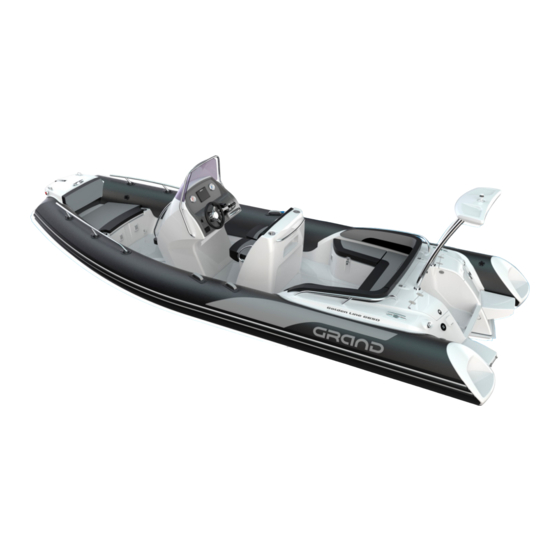
Page 90: General View Of A Boat
TECHNICAL DETAILS GENERAL VIEW OF A BOAT Fig. 53. General view of a boat. -
Page 91: Electrical Schematic Diagrams
TECHNICAL DETAILS ELECTRICAL SCHEMATIC DIAGRAMS Fig. 54. Electrical schematic diagram for a boat with nav. lights on the bow step plate. Golden Line G650 Owner’s Manual... - Page 92 TECHNICAL DETAILS Fig. 55. Electrical schematic diagram for a boat with nav. lights on the navigation arch.
-
Page 93: Service And Maintenance
SERVICE AND MAINTENANCE 6. SERVICE AND MAINTENANCE CLEANING Regularly clean your boat and make sure this is done before winterizing. For cleaning use household cleaner (non abrasive) and fresh water only! At all times keep the inflatable tube, vinyl and other boat parts free of any chemical spills, such as: o Gasoline, grease, oil and any other oily product. -
Page 94: Cleaning Of Tube
SERVICE AND MAINTENANCE CLEANING OF TUBE An important factor for the long life of tube fabric is regular adequate cleaning. The subsequent cleaning procedure is recommended: Rinse off with clear, tap water (approx. 20 °C). Use gentle soapy water (pH value neutral to slightly alkaline) to wash the tube by means of a ... -
Page 95: Airtightness Of The Inflatable Tube
SERVICE AND MAINTENANCE AIRTIGHTNESS OF THE INFLATABLE TUBE The tube is considered to be airtight if it retains the recommended inflation pressure for 8 hours. As the inflatable tube is a primary safety feature - check the airtightness of your boat regularly. - Page 96 SERVICE AND MAINTENANCE If you discover a significant reduction in pressure, but do not see any obvious sources of leakage: o Step 1: check the inflation/deflation valves and overpressure valves. o Step 2: check the major seams. o Step 3: check the tube material from top to bottom. Contact your Dealer for advice if necessary.
-
Page 97: Maintenance Of Stainless Steel
SERVICE AND MAINTENANCE MAINTENANCE OF STAINLESS STEEL We use only top quality stainless steels, which are resistant to corrosion. However, this may not be permanent and maintenance is sometimes required so: o Avoid contamination and scoring to the surface. o Frequently wash with fresh water. -
Page 98: Regular Inspections
SERVICE AND MAINTENANCE Winterize the motor, following the manufacturer’s instructions. 1. WHEN THE BOAT IS IN STORAGE MAKE SURE IT IS COVERED. 2. STORE THE BOAT AWAY FROM RODENTS. 3. AVOID SHARP FOLDS IN THE TUBE MATERIAL. REGULAR INSPECTIONS Check frequently all navigation lights, horn, VHF radio (if fitted), safety handles, handrails and all other safety related equipment. -
Page 99: Trailering
TRAILERING 7. TRAILERING The size and carrying capacity of the trailer should be suitable for the size and weight of your boat including the engine. Do not use a trailer that is too big or too small for your boat. Use a BUNK trailer. - Page 100 TRAILERING Note. All dimensions are in mm. Fig. 57. Measurements for the correct trailer.
- Page 101 TRAILERING Note. All dimensions are in mm. Fig. 58. Measurements for the correct trailer. Sections A-A&B-B. Golden Line G650 Owner’s Manual...
-
Page 102: Boat Towing
TRAILERING BOAT TOWING Before towing your boat please refer to the trailer manufacturer’s manual and also note the following: Make sure that the trailer provides adequate support for the keel and bunks that provide large contact areas for the hull. The boat is properly inflated and the cockpit and hull drain plugs are open. -
Page 103: Show Respect For The Environment
ENVIRONMENT 8. SHOW RESPECT FOR THE ENVIRONMENT REMEMBER THAT RESPONSIBLE BOATING BEGINS WITH YOU! Respect your environment by applying the following basic rules: • AVOID CREATING EXCESSIVE WASH. • KEEP OUT OF DESIGNATED SWIMMING AREAS. • RESPECT ALL ANIMAL LIFE. •... -
Page 104: Grand's Warranty
This warranty applies to new Grand Inflatable Boats purchased from an Authorised Grand Marine Reseller. By using the Grand Inflatable Boats, the owner and operator understands and agree to undertake all instructions in the Grand Owner’s Manual, and agrees to all warranty and liability terms and conditions contained in this warranty. WARRANTY PERIOD Grand warrants Grand branded components from the date of purchase for a period of: ... -
Page 105: Warranty Coverage
Inflatable tubes. This warranty is limited to repair, or at Grand option, replacement of parts suffering from any of the defects described above during the warranty period. The judgment of Grand is final concerning the extent of items covered under above warranty. -
Page 106: Warranty Exclusions
Damage caused by not following procedures and recommendations in the Grand Owner’s Manual. Operating the craft beyond the design category. -
Page 107: Warranty Certificate
WARRANTY WARRANTY CERTIFICATE Name of Customer: __________________________________ Address: ___________________________________________ City: ______________ Post code: _______________________ E-mail_____________ Phone number: ___________________ WIN (Serial number):__________________________________ Signature: __________________________________________ Dealer address: _____________________________________ City: ______________ Post code: _______________________ Date of purchase: ____________________________________ Seller and customer acknowledge by signing that seller handed and customer received hereinbefore boat including standard (optional, if relevant) equipment and manual in English and that the boat is without evident defects. -
Page 108: For Your Notes
FOR YOUR NOTES...
Need help?
Do you have a question about the Golden G650 and is the answer not in the manual?
Questions and answers