Table of Contents
Advertisement
OPERATION, SERVICE AND PARTS
INSTRUCTION MANUAL
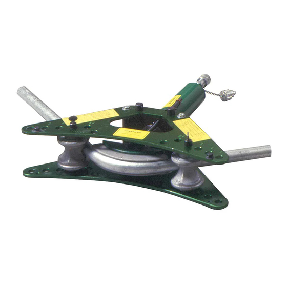
880
HYDRAULIC BENDER
Read and understand this material before
operating or servicing this tool. Failure
to understand how to safely operate this tool
could result in an accident causing serious
injury or death.
999 6196.2
© 2019 Greenlee Tools, Inc.
IM 689 REV 9
3/19
Advertisement
Table of Contents

Related Manuals for Greenlee 880


Summary of Contents for Greenlee 880
- Page 1 Read and understand this material before operating or servicing this tool. Failure to understand how to safely operate this tool could result in an accident causing serious injury or death. 999 6196.2 © 2019 Greenlee Tools, Inc. IM 689 REV 9 3/19...
-
Page 2: Table Of Contents
880 Hydraulic Bender Table of Contents Safe Operating Practices ...................2-3 Description and Purpose ..................3 Operating Instructions Setup....................... 4 Bending Conduit ..................... 5 Bending Instructions Glossary of Bending Terms (with Illustrations) ..........6 Laying Out One-Shot 90˚ Bends ..............7 Laying Out an Offset Bend ................ -
Page 3: Description And Purpose
40 pipe when used with standard aluminum bending operation and maintenance procedures for the 880 shoes. The 880 bends up to 90˚ in one shot. Conduit Bender. • Standard aluminum shoes bend 1" - 2" GRC and schedule 40 pipe. -
Page 4: Operating Instructions
880 Hydraulic Bender Operating Instructions Setup 1. Place the ram (A) between the two halves of the 6. Position the pipe support so that the side of the pipe frame unit (F). support facing the conduit corresponds to the size of conduit to be bent. -
Page 5: Bending Conduit
7. Repeat steps 5 and 6 until the last bend is made. 8. Remove the conduit from the bend. RAM TRAVEL SCALE Centerline Bending Radii for the 880 Bender Rigid Shoe Size 1-1/4 1-1/2... -
Page 6: Bending Instructions Glossary Of Bending Terms With Illustrations
880 Hydraulic Bender Bending Instructions Glossary of Bending Terms with Illustrations 1. amount of offset — the dis tance 11. 90˚ bend — any bend that chang- that the conduit or pipe must be es the direction of the conduit or re-routed to avoid an obstruction;... -
Page 7: Laying Out One-Shot 90˚ Bends
880 Hydraulic Bender Laying Out One-Shot 90˚ Bends 1. Measure the length of the required stub. See Figure 1. 2. Find the minimum stub length for that diameter of JUNCTION conduit on the Deduct and Minimum Stub Length Table. The stub you require must be equal to or lon- ger than the minimum stub length. -
Page 8: Laying Out An Offset Bend
19-5/16 2. Determine the angle of the offset bends. 3. Calculate the center-to-center distance. See the Greenlee Offset Multiplier and Shrink Table. Note: If working toward an obstruction, calculate the amount of shrink. See Calculating “Shrink” in this manual. -
Page 9: Calculating Shrink
Greenlee Offset Multiplier and Shrink Table. When laying out an offset and working away from an obstruction, no special provisions are required. -
Page 10: Laying Out A Segment Bend
880 Hydraulic Bender Laying Out a Segment Bend When a bend with a large radius is necessary, segment bending is required. Segment bending requires a series of small bends, or shots, spaced closely together. Use the formulas and tables that follow to mark the conduit. - Page 11 880 Hydraulic Bender Laying Out a Segment Bend (cont’d) Developed Length Formula for Any Bend developed length = 0.01744 x degree of bend x bending radius Developed Length Table RADIUS - Increments by Ones 1.57 3.14 4.71 6.28 7.85 9.42 10.99...
-
Page 12: Other Bending Information
880 Hydraulic Bender Laying Out a Segment Bend (cont’d) Suggested Number of Bends Table Suggested Number of Bends* Radius (minimum) (maximum) 4" - 10" 10" - 20" 20" - 30" 30" - 40" 40" - 50" 50" - 60" *The minimum and maximum number of bends are suggestions only. - Page 13 880 Hydraulic Bender Gain Factor Table ANGLE - Increments by Ones — 1˚ 2˚ 3˚ 4˚ 5˚ 6˚ 7˚ 8˚ 9˚ 0˚ .0000 .0000 .0000 .0000 .0000 .0000 .0001 .0001 .0003 .0003 10˚ .0005 .0006 .0008 .0010 .0013 .0015 .0018 .0022...
-
Page 14: Maintenance Exploded View And Parts List
880 Hydraulic Bender 880 Hydraulic Bender—Exploded View and Parts List Catalog No. Part No. Description 501 6249.7 15-Ton Ram with 4018GB female quick coupler (includes Keys C-E) ......1 1 1289 501 1289.9 3/8" x 6' High Pressure Hose with two 4033GB male quick couplers ......1 1 5289 501 5829.5... -
Page 15: Frame Unit-Parts Lists
880 Hydraulic Bender 2345AA Frame Unit (500 3396.4)—Parts List Cat. No. Part No. Description 2326AA 500 3368.9 Aluminum Cross Plate ..........2 2327AA 500 3369.7 Frame Support Pin .............2 1312AV 500 2767.0 Washer, 3/8 x 13/16 x 1/16, flat .........4 1313AV 500 2768.9... -
Page 16: Ram-Parts List
9A and 11A are for units built since December 1996. Use 9A and 11A if possible. 4455 Boeing Drive • Rockford, IL 61109-2988 • USA • 815-397-7070 USA Tel: 800-435-0786 Canada Tel: 800-435-0786 International Tel: +1-815-397-7070 ©2019 Greenlee Tools, Inc. • An ISO 9001 Company Fax: 800-451-2632 Fax: 800-524-2853 Fax: +1-815-397-9247 www.greenlee.com...
Need help?
Do you have a question about the 880 and is the answer not in the manual?
Questions and answers