Mighty Mule TS571W Installation Manual
Hide thumbs
Also See for TS571W:
- Installation manual ,
- Installation instructions manual (20 pages) ,
- Planning manual (2 pages)
Table of Contents
Advertisement
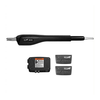
TS571W
Installation Manual
Leading Edge
of the gate
Gate Warning Sign
Control Box
Vehicular Gate
Sensing Edges
Photo Beams
Photo Beams
12 Volt Outdoor Marine
Battery & Weather Proof
(recommended, not included)
(recommended, not included)
(recommended, not included)
Housing
(Not included)
This product meets the requirements of UL325, the standard for gate operator safety.
Mighty Mule® is the retail brand of Nortek Security & Control, LLC
10022514 Rev-B
Advertisement
Table of Contents
Troubleshooting

Related Manuals for Mighty Mule TS571W


Summary of Contents for Mighty Mule TS571W
- Page 1 Battery & Weather Proof (recommended, not included) (recommended, not included) (recommended, not included) Housing (Not included) This product meets the requirements of UL325, the standard for gate operator safety. Mighty Mule® is the retail brand of Nortek Security & Control, LLC 10022514 Rev-B...
- Page 2 WARNING DO NOT SPLICE ANY POWER WIRES! DO NOT MODIFY THE BATTERY HARNESS! THIS WILL VOID YOUR MANUFACTURER’S WARRANTY. Low voltage wire for transformer not included.
- Page 3 Product Usage The Mighty Mule Gate Operator meets all of the safety requirements of a Class I Residential Vehicular Gate Operator and is intended for use solely with vehicular swing gates in single-family residential applications that meet the Class I category listed in the table below.
-
Page 4: Table Of Contents
Before You Begin ..........................12 Check Existing Gate Size and Material ............................13 IMPORTANT: Check for Proper Gate Installation ..........................13 Items Included for GATE OPERATOR Installation (TS571W) ......................14 Tools Needed ....................................15 Items Not Included ..................................15 Check Direction of Gate Swing ...............................15 Mechanical Installation ........................ -
Page 5: Please Read This First
When correctly installed and properly used, position, it can be set to remain open up to 120 seconds your Mighty Mule Gate Operator will give you many years before automatically closing. Pressing the transmitter of reliable service. Please read the following information... -
Page 6: Important Safety Information
Because Mighty Mule automatic gate operators are only part of the total gate operating system, it is the responsibility of the installer and end user to ensure that the total system is safe for its intended use. -
Page 7: For The Installer And End User
7. Identify all of the entrapment zones for the type of installation. An entrapment zone is an area around the automatic gate system where a person or object could be caught that increase the risk of injury. Entrapment zones should be eliminated, guarded or protected. TS571W Installation Instructions... - Page 8 Never install any control device where a user will be tempted to reach through the gate to activate the Driveway gate operator. 5. Secure outdoor or easily accessed gate operator controls in order to prohibit unauthorized use of the gate. Pull-To-Open Application TS571W Installation Instructions...
- Page 9 Contact Nortek Security & Control for free replacements. Should you need a replacement manual, a copy can be obtained by downloading one from the Mighty Mule 2. The gate is automatic and could move at any time, web site (www.mightymule.com), by contacting Nortek posing serious risk of entrapment.
- Page 10 Entrapment Alarm The Mighty Mule Automatic Gate Operator is designed to stop and reverse the gate when the gate comes in contact with an obstruction. Additionally, these operators are equipped with an audio entrapment alarm which will activate if the unit obstructs twice while opening or closing.
-
Page 11: Installing Warning Signs And Pedestrian Gates
INSTALLING WARNING SIGNS AND PEDESTRIAN GATES Warning signs alert people of automatic gate operation and are required when installing Mighty Mule Automatic Gate Operators. A minimum of two WARNING SIGNS must be installed in the area of the gate. Each sign is to be visible by persons located on the side of the gate on which the placard is installed. -
Page 12: Required Safety Precautions For Gates
Maximum Gate: 300 lb. (136 kg); 12 ft. (3.65 m) Voltage: 12 Vdc; Frequency: 0 Hz; Power: 25 W E472888 Class I Vehicular Gate Nortek Security & Control – Carlsbad, CA USA 10019665A Product identi cation label (1) installed on the side of the Control box. TS571W Installation Instructions... -
Page 13: Mighty Mule Ts571W Gate Opener
_____________________________________ POWER • The system is powered by a 12 Vdc automotive, lawn, tractor or marine battery (required but not included). A second Mighty Mule battery may be used (not included). • Battery charger is on the control board and maintained by a 120VAC to 19VDC output transformer or by optional Solar Panels; the panel should generate minimum of 10 Watts (600 mA/20 watt max.). -
Page 14: Powering Options
[FM123]. Refer to the Solar Panel and Gate Activity chart below. ● All low voltage wire used with the Mighty Mule gate operator must be 16 gauge dual conductor, stranded, direct burial wire [RB509]. Do not run more than 1000 ft. of wire. -
Page 15: Check Existing Gate Size And Material
2 ft. or Less from post protects against lightning strikes. If installed correctly, a grounding system will help minimize damage to your gate Copper ground 2 Inches or rod clamp Less above operator. ground 12awg or Larger Ground TS571W Installation Instructions... -
Page 16: Items Included For Gate Operator Installation (Ts571W)
ITEMS INCLUDED FOR GATE OPERATOR INSTALLATION (TS571W) RP1010 Transformer Operator Closed Position Stop Plate Literature kit with gate warning signs Gate Bracket Control Box, Antenna & Battery Harness MMT103 Transmitter Post Brackets (2) Post Pivot Bracket 8” Nylon Cable Tie (10) 3/8”... -
Page 17: Tools Needed
CHECK DIRECTION OF GATE SWING (Requires Push-To-Open Bracket #FM148—NOT INCLUDED) Your Property Your Property Pull-to-Open Option Push-to-Open Option Pull-To-Open Push-To-Open (arm retracts to open) (arm extends to open) Instructions begin on page 2. Instructions begin on page 8. TS571W Installation Instructions... -
Page 18: Mechanical Installation
(not supplied) Gate Bracket Thin Walled Tube Gate Muffler Clamp for Gate Bracket Gate Bracket Gate Bracket Wood or Metal Panel Reinforcement Gate (not supplied) 1" x 6" Wood Reinforcement Wood or Metal Reinforcement 1” x 6” Reinforcement TS571W Installation Instructions... -
Page 19: Pull-To-Open Operator Mounting ( Most Common )
PULL-TO-OPEN OPERATOR MOUNTING ( MOST COMMON ) Your Property Step 1 ● Assemble the gate post bracket sub assembly as displayed. Step 2 ● Attach the gate post bracket subassembly and gate bracket to the operator as shown. TS571W Installation Instructions... - Page 20 TIP: Turning the pivot bracket over Open gives more hole alignment options Position for the gate post pivot bracket assembly. WARNING: ENSURE THE REAR MOUNT DOES NOT MAKE CONTACT WITH THE POST-BRACKET ASSEMBLY DURING ANY POINT OF THE GATE TRAVEL. TS571W Installation Instructions...
- Page 21 ● Mark the center of the mounting locations for the gate bracket. Step 7 ● Remove the gate post and gate brackets. ● Use a hammer and center punch to mark the center of the mounting locations. TS571W Installation Instructions...
- Page 22 Note: Some installations may require additional reinforcement be installed on the gate. See page 16. Step 9 ● Secure the gate post bracket subassembly with the supplied hardware as shown. TS571W Installation Instructions...
- Page 23 ● Ensure the operator arm is level, adjusting the post bracket location if necessary. ● Once level, ensure all hardware is tight. ● Remove excess bolt length with a hacksaw. TS571W Installation Instructions...
-
Page 24: Installing The Closed Position Stop Plate / Pull-To-Open
● Tighten the mounting hardware. ● Return the gate to the open position and reinstall the operator Fence Post arm. ● To complete the pull-to-open installation, see page 17. TS571W Installation Instructions... -
Page 25: Push-To-Open Operator Mounting
Push-to-Open pivot 11” bracket (FM148) Step 2 ● Attach the gate post bracket subassembly and gate bracket to the operator as shown. ● The operator must be fully retracted with the gate in the desired open position. 11” TS571W Installation Instructions... - Page 26 20 inches. 20” MAX ● Make adjustments to the mounting brackets to achieve the recommended clearances. TIP: Turning the Push-to-Open bracket (sold separately) over gives more hole alignment options for the gate post pivot bracket assembly. TS571W Installation Instructions...
- Page 27 ● Mark the center of the mounting locations for the gate bracket. Step 7 ● Remove the gate post and gate brackets. ● Use a hammer and center punch to mark the center of the mounting locations. TS571W Installation Instructions...
- Page 28 Note: Some installations may require additional reinforcement be installed on the gate. See page 16. Step 9 ● Secure the gate post bracket subassembly with the supplied hardware as shown. TS571W Installation Instructions...
- Page 29 ● Ensure the operator arm is level, adjusting the post bracket location if necessary. ● Once level, ensure all hardware is tight. ● Remove excess bolt length with a hacksaw. TS571W Installation Instructions...
-
Page 30: Installing The Closed Position Stop Plate / Push-To-Open
Step 2 ● Swing the gate to the closed position, and adjust the closed position stop plate against the fence post. ● Tighten the mounting hardware. ● With the gate in the closed position, reinstall the operator arm. TS571W Installation Instructions... -
Page 31: Control Box Installation
● Install the Antenna by screwing it in place on the SMA connector. ● Orient the antenna to the sky, and securely tighten. ● Be certain to point the antenna straight up TS571W / TS571W Installation Instructions TS571W Installation Instructions... -
Page 32: Connecting The Operator And Battery
Step 2 RESET ● Insert the operator cable and battery harness through the cables glands into the control box. BAT+ BAT– ● Once inserted, secure the cables in place by tightening the sealing nuts. LOCK SECURE SEALING NUT TS571W Installation Instructions... - Page 33 Black (BAT–). BAT– 1 2 3 4 5 RESET AUTO CLOSE TERM6 BAT+ – BAT– BAT T – B AT T + LOCK SW 1– S W1 + BAT T – B AT T + Battery Power Access TS571W Installation Instructions...
-
Page 34: Transformer Or Solar Panel Wiring Installation
● Along the identified path between outlet and control box, dig a trench to lay the low voltage transformer wire (RB509 sold separately). ● Use PVC conduit from the ground up to the control box. ● Recommend conduit in trench TS571W Installation Instructions... - Page 35 -. ● Plug the transformer into the selected LOCK S W 1 – electrical outlet. S W1 + Note: Use of a surge protector is strongly – recommended. ery Power Access TS571W Installation Instructions...
-
Page 36: Electrical Installation And Setup
CLOSE ● The system will take approximately 20 seconds to power up indicated by an audible tone and LED D17 will flash. 3. Warning ● The WARNING DIP switch toggles a movement alarm ON or OFF. LOCK TS571W Installation Instructions... -
Page 37: Transmitter Programming
2. Press and hold the (down arrow) button until LED1, 2 & 3 flash and the buzzer sounds. (Approximately 10 seconds.) Note: The control board can store a total of 50 transmitter and/or keypad codes. The system is compatible with Mighty Mule DIP switch transmitters and keypads. -
Page 38: Closed Limit Programming - Pull To Open
You do not have to start the positioning all over. If the closed position is already correct but you have timed out, press and hold and until the buzzer sounds, then release. Then, immediately press and hold until the buzzer sounds and then release. TS571W Installation Instructions... - Page 39 You do not have to start the positioning all over. If the open position is already correct but you have timed out, press and hold and until the buzzer sounds, then release. Then, immediately press and hold until the buzzer sounds and then release. TS571W Installation Instructions...
-
Page 40: Dual Sense Stall Force Setting
2. Use the or to adjust the Stall Force setting. LED1, 2, & 3 are used to indicate the setting. LED3 ON indicates LOW, LED3 & 2 ON indicates MEDIUM, and LED1, 2 & 3 ON indicates HIGH. 3. Press until the buzzer sounds then release to set the Stall Force setting. TS571W Installation Instructions... -
Page 41: Auto Close Setting
This product has the ability of being control via a smart device (i.e. smartphone) with the addition of the MMS100 smart kit. Refer to the instructions contained in the MMS100 kit or visit www.mightymule.com for more information TS571W Installation Instructions... -
Page 42: Connecting Additional Devices
Connecting Additional Devices Mighty Mule strongly recommends the use of additional obstruction detection devices however we do not endorse any specific brand names. Only use products that are listed to be in compliance with any applicable UL safety standards and national and regional codes. -
Page 43: Control Board Connections
See page 42 of this manual for connection diagram. The LOCK Relay should only be used for switching LOCK V-. NOTE: DO NOT connect positive voltage to the AUX or LOCK Relays. TS571W Installation Instructions... -
Page 44: Connecting Accessories
NOTE: Connections are for typical applications. For additional connection options not illustrated here refer to the accessory manual for details. Mighty Mule Vehicle Sensor For FM130/FM130-SW and FM136, Refer to the Vehicle Sensor Manual for additional information if needed. see Appendix A in this manual. -
Page 45: Maintenance
● Monthly, turn off the power switch and disconnect the Mighty Mule and move the gate to make sure the gate is moving freely without sticking or binding. Lubricate the hinges or repair the gate as required before reattaching the Mighty Mule. -
Page 46: Troubleshooting Guide - Audible Feedback
Check fuses The unit clicks with no arm Internal motor problem or low h Battery harness connections movement battery h Battery under load h Inadequate charge Additional information can be found by contacting Nortek Security & Control. TS571W Installation Instructions... -
Page 47: Troubleshooting Guide - Visual Feedback
AC output at 120 Vac, transformer output at 19 Vdc h Solar panel(s) output based on weather conditions h Wiring from charge source to control board, verify correct polarity Connect battery/batteries Charge LED Flashing Battery or Batteries disconnected TS571W Installation Instructions... - Page 48 Check battery connections and harness, ensure the battery is incorrectly connected red to red (+) and black to black (-) h Replace harness fuse and F2 fuse if blown Additional information can be found by contacting Nortek Security & Control. TS571W Installation Instructions...
- Page 49 TS571W Installation Instructions...
-
Page 50: Repair Service
Repair Service If your Mighty Mule Gate Opener is not operating properly, please follow the steps below: 4. If repair or replacement of your gate operator is necessary, 1. First use the procedures found in the the Service Department will assign a Return Authorization Maintenance (see page 43) &... -
Page 51: Accessories
Mighty Mule gate openers. One remote for two or three devices. Pin Lock (FM133) The Pin Lock substitutes for the clevis pin at the front end of the Mighty Mule gate operators. Helps prevent theft of the operator from the gate, while allowing quick release of the operator. - Page 52 Nortek Security & Control. Any reprinting of Nortek Security & Control publications is by permission only. Copyright infringement is a violation of federal law. Mighty Mule¨, E-Z Gate¨, Nortek Security and Control¨, “Dual Sense Technology” are registered trademarks of Nortek Security & Control, LLC, America’s DIY Automatic Gate Openers is a trademark of Nortek Security &...
-
Page 53: Accessory Installation Instructions
LED2 will flash and the buzzer will sound on the gate operator control board. Proceed with installation of the FM136 per the accessory instructions. Notes: 1. If you need to erase this device, repeat steps 2-3 above. 2. Erasing all transmitters on the gate operator control board will erase this device. TS571W Installation Instructions... -
Page 54: Gate Operator Installation Checklist
Copyright infringement is a violation of federal law. Mighty Mule¨, E-Z Gate¨, NSC¨, “Dual Sense Technology” are registered trademarks of Nortek Security & Control, LLC, America’s DIY Automatic Gate Openers is a trademark of Nortek Security & Control, LLC and are the exclusive property of Nortek Security &...
Need help?
Do you have a question about the TS571W and is the answer not in the manual?
Questions and answers