Chapters
Table of Contents

Subscribe to Our Youtube Channel
Related Manuals for GLW MC 25

Summary of Contents for GLW MC 25
- Page 1 MC25 Betriebsanleitung MC 25 Operating Manual MC 25 Mode d´emploi MC 25 Manual de instrucciones MC 25 Ausgabedatum /Date of issue/ Date d'édition/ Fecha de edición: 01/2020...
- Page 2 MC25...
- Page 3 MC25 Betriebsanleitung MC 25 Ausgabedatum: 01/2020 Für künftige Verwendung aufbewahren!
- Page 4 MC25...
-
Page 5: Table Of Contents
Inhalt Sicherheit 1 - 3 Grundlegende Hinweise Symbole Gefährlichkeit der Maschine Bestimmungsgemäße Verwendung Gefahrenquellen Arbeitsplätze Schutzeinrichtungen Zugelassene Bediener Gewährleistung Beschreibung 4 - 8 Lieferumfang Verwendung Bedienteile-Übersicht Bedienteile-Funktion Inbetriebnahme 9 - 11 Bedienung 12 - 13 Umrüsten 14 - 15 Störungen Selbsthilfe 17 - 23 Ersatzteile... - Page 6 10/12...
-
Page 7: Sicherheit
Kenntnis und Beachtung der Sicherheitshinweise. Es geht um Ihre Sicherheit! Die Sicherheitshinweise sind von allen Personen zu beachten, die mit dem MC 25 arbeiten. Darüber hinaus sind die für den Einsatzort geltenden Regeln und Vorschriften, insbesondere zur Unfallverhütung, zu beachten. -
Page 8: Bestimmungsgemäße Verwendung
Dabei dürfen nur Aderendhülsen mit den Querschnitten 0,5 bis 2,5 mm und einer Länge von 8 mm benutzt werden. In den Einführungstrichter am MC 25 dürfen nur die zur Verarbeitung vorgesehenen PVC-isolier- ten Leiter eingeführt werden. Auf keinen Fall massive Metallteile o. ä. Gegenstände. Die Abisoliermesser würden zerstört. -
Page 9: Schutzeinrichtungen
Umbauten umgangen werden. Ein Schild weist auf bestehende Gefahren hin. Zugelassene Bediener Am MC 25 dürfen nur autorisierte und eingewiesene Bediener arbeiten. Der Bediener ist im Arbeitsbereich Dritten gegenüber verantwortlich. Der Betreiber muss dem Bediener die Betriebsanleitung zugänglich machen und ... -
Page 10: Beschreibung
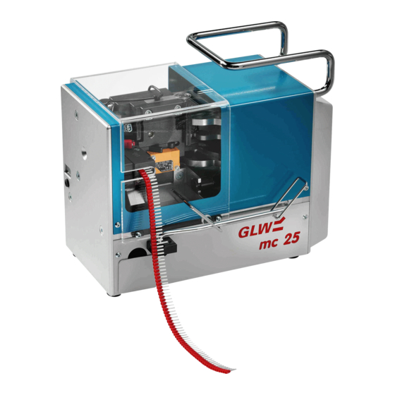
Beschreibung Lieferumfang Bild 1 Lieferumfang 1 MC 25 1 Stück 5 Zubehörkoffer 1 Stück Inhalt: 2 Netzkabel 1 Stück 3 Schublade für Isolationsreste 1 Stück 6 Hülsenzuführung für 5 Stück 4 Betriebsanleitung deutsch 1 Stück Aderendhülsen 0,5 bis 2,5 mm bei Auslandslieferung zusätzl. -
Page 11: Verwendung
Verarbeitet werden Aderhülsen nach DIN 46228 Teil 4 im Querschnitt 0,5 bis 2,5 mm² mit 8 mm Abisolierlänge. Aufgrund kurzer Taktzeiten (1,5 s) und dem problemlosen Querschnittswechsel (unter 10 s) ist der MC 25 ebenso für den Einsatz in Werkstätten als auch in komplexen Kabel- konfektions-Systemen geeignet. -
Page 12: Bedienteile-Übersicht
Beschreibung Bedienteile-Übersicht Bild 2 Bedienteile 1 Tragegriff Netzanschluss 2 Einführungstrichter 10 Netzsicherungen 3 Stückzähler 11 Netzschalter 4 Rückstell-Taste 12 Trafosicherungen 5 Bearbeitungseinsatz 13 Reverse-Taste 6 Sicherungsbolzen 14 Spender-Halter 7 Schutzhaube 15 Schublade 8 Hülsenzuführung 10/12... -
Page 13: Bedienteile-Funktion
Nimmt das Aderendhülsen-Band auf. Für jeden Querschnitt ist die zugehörige Hülsenzuführung einzusetzen. 9 Netzanschluss Geräteanschluss für das Netzkabel. 10 Netzsicherungen Im Netzanschluss integrierte Feinsicherungen. 11 Netzschalter Schaltet die Stromversorgung für den MC 25 ein (I gedrückt) oder aus (0 gedrückt). 10/12... - Page 14 12 Trafosicherungen Sekundärseitige Gerätesicherung mit Feinsicherungen 4,0 A/T/250 V. 13 Reverse-Taste Nach Drücken der Taste fährt der MC 25 in eine Wartungsstellung zurück. Nach nochmaligem Drücken fährt der MC 25 in Startposition vor. 14 Spender-Halter Haltert das rollenförmig im Spender liegende Aderendhülsen-Band.
-
Page 15: Inbetriebnahme
INBETRIEBNAHME 1. Wahl des Aufstellungsortes Der Aufstellungsort muss eben und waagrecht sein. Die Bedingungen in Kapitel Sicherheit, Abschnitt Arbeitsplätze, sind zu beachten. 2. Spender vorbereiten Spender öffnen und Lasche an Kante (1) abreißen. Aderendhülsen-Band (2) ca. 20 cm herausziehen. - Page 16 INBETRIEBNAHME 4. Hülsenzuführung montieren Bearbeitungseinsatz darf noch nicht montiert sein. Schutzhaube (1) zurückschieben. Hülsenzuführung (2) seitlich einsetzen und auf die Bolzen (3) drücken. Einrastung prüfen. Bild 5 Hülsenzuführung montieren 5. Spender aufsetzen Spender (1) auf Halter aufsetzen und andrücken.
- Page 17 Spender (1) in Betriebsstellung klappen. Schutzhaube (2) schließen. Darauf achten, dass Aderendhülsen- Band ungehindert einlaufen kann. Netzstecker (3) am Netzanschluß des MC 25 und Schukostecker (4) an Netzsteckdose anschließen. Bild 8 Betriebsbereitschaft herstellen Anschließend kann mit der Bedienung fortgefahren werden.
-
Page 18: Bedienung
Bild 10 Leiter zuschneiden Bild 11 Falscher Leiterzuschnitt 3. MC 25 einschalten Prüfen, ob Schutzhaube (1) geschlossen ist. MC 25 mit Netzschalter (2) einschalten (I gedrückt). Prüfen, ob Stückzähler (3) 0 anzeigt. Zeigt der Stückzähler nicht 0 an, so ist Kapitel Störungen zu Rate zu ziehen. - Page 19 Leiter (1) geradlinig bis zum Anschlag in den Einführungstrichter schieben. Der Abisolier- und Crimpvorgang erfolgt automatisch. Nach Stillstand des MC 25 Leiter (2) geradlinig herausziehen. Bei Betriebsstörungen bzw. unsachgemäßer Crimpung ist Kapitel Störungen zu Rate zu ziehen.
-
Page 20: Umrüsten
UMRÜSTEN 1. Umrüstung vorbereiten Schutzhaube muss geöffnet werden, Netzstecker ziehen! Ggf. Stückzähler ablesen. MC 25 mit Netzschalter (1) ausschalten (0 gedrückt). Netzstecker (2) ziehen. Schutzhaube (3) zurückschieben. Stift (4) nach oben ziehen, Adernhülsen (5) herausziehen. - Page 21 UMRÜSTEN 3. Hülsenzuführung ausbauen Hülsenzuführung (1) nach hinten ziehen und seitlich (2) entnehmen. Hülsenzuführung im Zubehörkoffer verstauen. Bild 18 Hülsenzuführung ausbauen Anschließend gemäß Abschnitt Inbetriebnahme Schritt 2. bis 7. fortfahren. 10/12...
- Page 22 Leiterisolation wird unvollständig entfernt. Störungsbild 5 Aderendhülse wird nicht vom Band getrennt. Störungsbild 6 Stückzähler zeigt nicht an, bzw. MC 25 läßt sich nicht einschalten. Störungsbild 7 MC 25 arbeitet zu langsam, Stückzähler zeigt jedoch an. Störungsbild 8 Crimpgesenk oder Crimpstempel defekt.
-
Page 23: Selbsthilfe
Leiter kann nicht eingeführt werden. Der Leiter kann nur in Startposition (vorne), nicht in Wartungsstellung (hinten) eingeführt werden. Reverse-Taste (1) drücken, MC 25 fährt in Start- position. Der Leiter kann eingeführt werden. Bild 19 MC 25 in Startposition fahren Störungsbild 2 Crimpvorgang wird nicht beendet. - Page 24 MC 25 mit Netzschalter (5) einschalten (I gedrückt) Reverse-Taste (6) drücken, MC 25 fährt in Startposition. Leiter (7) herausziehen. Bild 22 Leiter entnehmen Nach Einbau des Bearbeitungseinsatzes und Einlegen der Aderendhülsen ist der MC 25 wieder betriebsbereit. 10/12...
- Page 25 Crimpvorgang wird beendet. Leiter lässt sich jedoch nicht herausziehen. Schutzhaube muss geöffnet werden, Netzstecker ziehen! 1. Außer Betrieb setzen Ggf. Stückzähler (1) ablesen. Reverse-Taste (2) drücken, MC 25 fährt in Wartungsstellung. MC 25 mit Netzschalter (3) ausschalten (0 gedrückt). Netzstecker (4) ziehen.
- Page 26 Stift (1) nach oben ziehen, Aderendhülsen (2) herausziehen. Schutzhaube (3) schließen. Netzstecker (4) anschließen. MC 25 mit Netzschalter (5) einschalten. Reverse-Taste (6) drücken, MC 25 fährt in Startposition. Leiter (7) herausziehen. Nach Einbau des Bearbeitungseinsatzes und Bild 25 Leiter entnehmen Einlegen der Aderendhülsen ist der MC 25 wieder...
- Page 27 SELBSTHILFE Störungsbild 4 Leiterisolation wird unvollständig entfernt. Schutzhaube muss geöffnet werden, Netzstecker ziehen! 1. Querschnittsangaben überprüfen Bei fehlerhafter Abisolierung des Leiters ist als erstes zu überprüfen, ob der gewählte Leiter- querschnitt mit der Querschnittsangabe des Bearbeitungseinsatzes und der Hülsenzuführung übereinstimmt. Bei fehlerhafter Bestückung sind die Einsätze dem gewählten Leiterquerschnitt anzupassen.
- Page 28 Stückzähler zeigt nicht an, bzw. MC 25 lässt sich nicht einschalten. 1. Netzanschluss prüfen Prüfen Sie, ob der Netzstecker am Netzanschluss des MC 25 und der Schukostecker an der Netz- steckdose angeschlossen sind. Vergewissern Sie sich, dass die Stromversorgung an der Netz- steckdose i.
- Page 29 SELBSTHILFE Störungsbild 7 MC 25 arbeitet zu langsam, Stückzähler zeigt jedoch an. Gerätesicherungen müssen ent- nommen werden, Netzstecker ziehen! Netzstecker (1) ziehen. Sicherungshalter (2) herausdrehen. Gerätesicherungen (3) prüfen. Defekte Gerätesicherung ersetzen. Die zuge- hörige Artikel-Nr. ist aus Kapitel Ersatzteile ersichtlich.
- Page 30 SPARE PARTS Teil Querschnitt Artikel-Nr. Liefermenge 0.5 mm² MC2SCH05 004943 Bearbeitungseinsatz 0.75 mm² MC2SCH07 004944 1.0 mm² MC2SCH10 004945 1.5 mm² MC2SCH15 004946 2.5 mm² MC2SCH25 004947 0.5 mm² MC2AM05 004938 Abisoliermesser 0.75 mm² MC2AM07 004939 1.0 mm² MC2AM10 004940 1.5 mm²...
-
Page 31: Ersatzteile
ERSATZTEILE Teil Querschnitt Artikel-Nr. Liefermenge Netzsicherung MC2SI0.63 006202 (230V-Version) 230 V: T 0,63 A MC2SI1.25 115 V: T 1,25 A (115V-Version) Gerätesicherung MC2SI4.0 006494 T 4,0 A Crimpgesenk MC2CGES 004932 Crimpstempel MC2CSTE 004933 Zentriergabel unten MC2 0011 007059 Zentriergabel oben MC2 0013 007058 mit Luftschlauch... -
Page 32: Technische Daten
TECHNISCHE DATEN Netzanschluss ..................230 V/50 Hz(115 V/60Hz) Leistungsaufnahme ........................80 VA Arbeitsbereich ..................0,5 - 2,5 mm² 20 - 14 AWG Aderendhülsen ................in Bandform nach DIN 46228 Teil 4 Verpressung ........................trapezförmig Takt............................1,5 s Steuerung ..............microprozessorunterstützte Kurvensteuerung Stückzähler ........................ -
Page 33: Eg Konformitätserklärung
Produktbezeichnung / Product description: MC 25 MC 25 US (120 V) Das vorstehend bezeichnete Produkt stimmt mit den wesentlichen Anforderungen der nachfolgenden Richtlinie(n) und deren Änderungsrichtlinien überein / The above mentioned product is in line with the essential requirements of the below directive(s) and their modification directive(s):... - Page 34 GLW GmbH Das Urheberrecht an dieser Betriebsanleitung Steinbeisstraße 2 verbleibt bei der Firma GLW. 88353 Kisslegg Nachdruck, Vervielfältigung oder Übersetzung, Deutschland auch auszugsweise, sind ohne Genehmigung Tel. (07563) 9123-0 nicht gestattet. Fax (07563) 9123-99 2020 GLW GmbH...
- Page 35 MC 25 Instruction for use MC 25 Date of issue: 01/2020 Save this instruction for further use!
- Page 36 MC 25...
- Page 37 Safety 1 - 3 Basic information Symbols Danger of machine Dedicated usage Dangers Places for use Safety devices Authorized user Warranty Description 4 - 8 Extent of Delivery Usage Standard components overview Standard components functions Commissioning 9 - 11 Operation 12 - 13 Retooling 14 - 15...
- Page 38 10/12...
- Page 39 SAFETY Basic information The basic condition for safe use and proper work of the mc 25 is the knowledge and attention of the safety information. Important for your safety! The following safety information must be observed by all persons who will work with the mc 25.
- Page 40 8 mm must be used. Only the intended PVC insulated cables may be inserted into the funnel guide of the mc 25. Never insert solid metal parts or items. The stripping knifes would be damaged.
- Page 41 Authorized user Only authorized and instructed users are allowed to work with the mc 25. The user has a responsibility to other persons inside the mc 25 working place. The customer must make the instruction for use accessible to the user and ...
- Page 42 DESCRIPTION Extent of Delivery Diagram 1 Extent of delivery 1 MC 25 1 piece 5 Accessories box 1 piece 2 Mains cable 1 piece Content: 3 Container for insulation scrap 1 piece 6 Feeder blocks for end sleeves 5 pieces...
- Page 43 8 mm. Due to the short cycle times (1.5 s) and simple changing of cross-sections (below 10 s) the mc 25 is not only suitable for use in workshops but also in complex cable production systems.
- Page 44 DESCRIPTION Standard components overview Diagram 2 Standard components 1 Grip Mains connection 2 Funnel guide 10 Mains fuses 3 Counter 11 Mains switch 4 Reset button 12 Transformer fuses 5 Tool insert 13 Reverse button 6 Bolt 14 End-sleeve dispenser holder 7 Cover 15 Container 8 End-sleeve feeder...
- Page 45 1 Grip For transport of the mc 25. 2 Funnel guide The cable to be processed is inserted into the mc 25 through the funnel guide. Once it has been inserted, work commences automatically. 3 Counter (000000 to 999999) The counter counts the number of end-sleeves used.
- Page 46 12 Transformer fuses One 4.0 A/T/250 V fine wire fuse for secondary device. 13 Reverse button Pressing this button puts the mc 25 in the maintenance position. Pressing again will put the mc 25 in start position. 14 End-sleeve dispenser holder Holds the end-sleeves reel dispenser.
- Page 47 COMMISSIONING 1. Chose the installation site The installation site of the mc 25 must be level and horizontal. Observe the working conditions in chapter safety, section places for use. 2. Prepare the dispenser Open the dispenser and tear-off the strap at the edge (1).
- Page 48 COMMISSIONING 4. Fit the end-sleeve feeder Verify that the tool insert is not installed yet. Slide the cover (1) back. Insert the end-sleeve feeder (2) sideways and place it on the bolts (3). Check that the end-sleeve feeder has clicked properly into place.
- Page 49 Close the cover (2). Be sure that the end-sleeves band is fed properly. Connect the mains cable with the appropriate connectors (3,4) to the mc 25 and the mains supply. Diagram 8 Place to operation mode The mc 25 is now ready for operation.
- Page 50 Poor cut 3. Start the mc 25 Check that the cover (1) is closed. Turn on (position I) the mc 25 with the mains switch (2). Check that counter (3) is at 0. If the counter is not at 0 refer to chapter faults.
- Page 51 Insert the cable (1) straight into the funnel guide until it stops. Crimping and stripping works automatically. Pull out the cable (2) straight when the mc 25 has stopped. Refer to chapter faults when operating faults or unsuccessful crimping occurs.
- Page 52 Disconnect the mains supply from the mc 25 and open cover. Read counter if required. Turn off the mc 25 with mains switch (1). Disconnect mains cable (2). Slide back the cover (3). Pull the pin (4) upwards and pull out the end sleeves (5).
- Page 53 RETOOLING 3. Remove the end-sleeve feeder Pull the end-sleeve feeder (1) towards the rear and remove it sideways (2). Put the end-sleeve feeder into the accessories box. Diagram 18 Remove the end-sleeve feeder Continue as described with step 2 to 7 in chapter commissioning. 10/12...
- Page 54 The end sleeve is not separated from band. Fault condition 6 Counter respectively mc 25 do not work. Fault condition 7 The mc 25 works too slow but counter works. Fault condition 8 Crimp stamp or crimp forging die is defective. 01/97...
- Page 55 Cable cannot be inserted. Cable can only be inserted in start position (front) and not in maintenance position (rear). Press the reverse button (1) to move the mc 25 into start position. Diagram 19 Move the mc 25 into start...
- Page 56 Press the reverse button (6) to move the mc 25 into start position. Pull out the cable (7). Diagram 22 Remove the cable After mounting the tool insert and insertion of the end sleeves the mc 25 is ready for operation. 10/12...
- Page 57 25 and open cover. 1. Stop operation Read counter (1) if required. Press the reverse button (2) to move the mc 25 into start position. Turn off (position 0) the mc 25 with mains switch (3).
- Page 58 Pull the pin (1) upwards and pull out the end sleeves (2). Close the cover (3). Connect mains cable (4). Turn on (position I) the mc 25 with the mains switch (5). Press the reverse button (6) to move the mc 25 into start position.
- Page 59 If stripping is faulty, check whether the selected cable cross-section corresponds to the cross- section size of the tool insert and the end-sleeve feeder block. The tool inserts must be adapted to the cable cross-section if the mc 25 has not been properly tooled. The cross-section of the cable must also be checked.
- Page 60 Counter respectively mc 25 do not work. 1. Check mains connection Check that the mains cable is connected with the appropriate connectors to the mc 25 and the mains supply. Make sure that you have supply to the plug socket is properly.
- Page 61 TROUBLE-SHOOTING Fault condition 7 The mc 25 works too slow but counter works. Remove mains fuses, disconnect the mc 25 from mains! Pull out mains plug (1). Unscrew the fuse holder (2). Check the device fuses (3).
- Page 62 SPARE PARTS Part Cross Section Art. No. Packing unit 0.5 mm² MC2SCH05 004943 Tool insert 0.75 mm² MC2SCH07 004944 1.0 mm² MC2SCH10 004945 1.5 mm² MC2SCH15 004946 2.5 mm² MC2SCH25 004947 0.5 mm² MC2AM05 004938 Stripping cutter 0.75 mm² MC2AM07 004939 1.0 mm²...
- Page 63 SPARE PARTS Part Cross Section Art. No. Packing unit MC2SI0.63 Mains fuse 006202 (230V- 230 V: T 0,63 A Version) 115 V: T 1,25 A MC2SI1.25 (115V- Version) Device fuse MC2SI4.0 006494 T 4,0 A Crimp die MC2CGES 004932 Crimp stamp MC2CSTE 004933 centring fork bottom...
- Page 64 TECHNICAL DATA Mains supply .................... 230 V/50 Hz(115 V/60 Hz) Power consumption .........................80 VA Working range ..................0.5 - 2.5 mm² 20 - 14 AWG End sleeves ................. In Bands acc. to DIN 46228 Part 4 Press form ......................Trapezium shaped Cycle time ..........................
- Page 65 Produktbezeichnung / Product description: MC 25 MC 25 US (120 V) Das vorstehend bezeichnete Produkt stimmt mit den wesentlichen Anforderungen der nachfolgenden Richtlinie(n) und deren Änderungsrichtlinien überein / The above mentioned product is in line with the essential requirements of the below directive(s) and their modification directive(s):...
- Page 66 The copyright for this instruction for use remains Steinbeisstr. 2 by GLW. 88353 Kisslegg No part of this instruction for use may be Germany reproduced, copied or translated without Phone (+49) 7563 9123-0 permission. Telefax (+49) 7563 9123-99 2020 GLW GmbH...
- Page 67 Instructions d’emploi MC 25 Date d’ édition: 01/2020 A conserver pour utilisation ultérieure!
- Page 69 SOMMAIRE Sécurité 1 - 3 Règles fondamentales Symboles Dangerosité de la machine Utilisation conforme Sources de dangers Emplacements de travail Equipements de protection Utilisateurs autorisés Garantie Description 4 - 8 Fournitures Application Liste des éléments fonctionnels Fonction des éléments fonctionnels Mise en service 9 - 11 Utilisation...
- Page 70 10/12...
-
Page 71: Sécurité
Le mc 25 doit être utilisé uniquement pour l'usage prévu et en parfait état technique. Toutes les personnes amenées à effectuer la mise en service du mc 25, à l'utiliser ou à en assurer l'entretien doivent posséder les qualifications nécessaires et ... -
Page 72: Utilisation Conforme
8 mm. Seuls les conducteurs à isolant PVC prévus doivent être introduits dans le cône d'introduction du mc 25. N'introduire en aucun cas de pièces en métal massif ou d'autres objets, ce qui détruirait les couteaux à dénuder. -
Page 73: Equipements De Protection
Une plaque signale les dangers existants. Utilisateurs autorisés Le mc 25 doit être utilisé uniquement par des personnes autorisées et formées en conséquence. A l'intérieur de l'espace de travail, l'utilisateur est responsable vis à vis des tiers. L'exploitant doit ... -
Page 74: Description
DESCRIPTION Fournitures Figure 1 Fournitures 1 MC 25 1 unité 5 Mallette à accessoires 1 unité Contenu: 2 Cordon secteur 1 unité 3 Tiroir pour les chutes d'isolant 1 unité 6 Alimentateur pour embouts 5 unités 4 Instructions d'emploi en 1 unité... -
Page 75: Application
à dénuder de 8 mm. Compte tenu des temps de cycles courts (1,5 s) et du changement aisé de section (moins de 10 s), le mc 25 peut être utilisé aussi bien en atelier qu'au sein de systèmes complexes de confection de câbles. -
Page 76: Liste Des Éléments Fonctionnels
DESCRIPTION Liste des éléments fonctionnels Figure 2 Eléments fonctionnels 1 Poignée de transport Connecteur secteur 2 Cône d'introduction 10 Fusibles secteur 3 Compteur 11 Interrupteur secteur 4 Touche de remise à zéro 12 Fusibles du transformateur 5 Insert de sertissage 13 Touche Retour 6 Goujon de fixation 14 Support de rouleau... -
Page 77: Fonction Des Éléments Fonctionnels
1 Poignée de transport Sert au transport du mc 25. 2 Cône d'introduction Le conducteur à sertir est introduit dans le mc 25 au travers de ce cône. Une fois introduit, les opérations commencent automatiquement. 3 Compteur (000000 à 999999) Le compteur indique le nombre d'embouts sertis. - Page 78 13 Touche Retour Lorsque cette touche a été enfoncée, le mc 25 revient en position d'attente. En enfonçant une nouvelle fois la touche, le mc 25 avance en position de départ. 14 Support de rouleau Tient la bande d'embouts enroulée dans le rouleau.
-
Page 79: Mise En Service
MISE EN SERVICE 1. Choix du lieu d'installation Le lieu d'installation doit être plan et horizontal. Observer les conditions indiquées au chapitre Sécurité, paragraphe Emplacements de travail. 2. Préparer le rouleau Ouvrir le rouleau et arracher la patte au bord (1). - Page 80 MISE EN SERVICE 4. Monter l'alimentateur pour embouts L'insert de sertissage ne doit pas encore être monté. Ramener le capot de protection (1) en arrière. Mettre en place l'alimentateur pour embouts (2) par le côté et le pousser sur le goujon (3). Vérifier l'enclenchement.
- Page 81 S'assurer que la bande d'embouts puisse rentrer sans être gênée. Brancher la fiche secteur (3) sur le connecteur secteur du mc 25 et la fiche de sécurité (4) sur la prise de courant. Figure 8 Mettre l'appareil en ordre de marche L'appareil peut ensuite être utilisé.
-
Page 82: Utilisation
Coupe incorrecte du conducteur 3. Mettre le mc 25 en marche Vérifier si le capot de protection (1) est fermé. Mettre le mc 25 en marche avec l'interrupteur secteur (2) (I enfoncé). Vérifier si le compteur (3) indique 0. - Page 83 Le conducteur est dénudé et serti automatiquement. Une fois le mc 25 arrêté, tirer le conducteur (2) de manière rectiligne. En cas de dérangement ou de sertissage incorrect, consulter le chapitre Dérangements ...
-
Page 84: Rééquipement
L’ouverture du capot de protection est nécessaire: débrancher la fiche secteur! Le cas échéant, consulter le compteur. Eteindre le mc 25 avec l’interrupteur secteur (1) (0 enfoncé). Débrancher la fiche secteur (2). Glisser le capot de protection (3) en arrière. - Page 85 REEQUIPEMENT 3. Démonter l’alimentateur pour embouts Tirer l’alimentateur (1) en arrière et le retirer latéralement (2). Ranger l’alimentateur pour embouts dans la mallette à accessoires. Démonter l’alimentateur pour Figure 18 embouts Poursuivre ensuite comme indiqué sous Mise en service, étapes 2. à 7. 10/12...
-
Page 86: Dérangements
L'embout n'est pas séparé de la bande. Manifestation du dérangement 6 Le compteur n'indique rien ou le mc 25 ne peut pas être mis en marche. Manifestation du dérangement 7 Le mc 25 fonctionne trop lentement mais le compteur indique une valeur. -
Page 87: Dépannage
Le conducteur ne peut pas être introduit. Le conducteur peut être introduit uniquement en position de départ (devant) mais pas en position d'attente (derrière). Actionner la touche Retour (1). Le mc 25 rejoint la position de départ. Le conducteur peut être introduit. Figure 19 Amener le mc 25 en position de départ... - Page 88 Actionner la touche Retour (6), le mc 25 rejoint la position de départ. Retirer le conducteur (7). Figure 22 Retirer le conducteur Après avoir monté l'insert de sertissage et mis en place les embouts, le mc 25 est de nouveau en ordre de marche. 03/2016...
- Page 89 1. Mettre l'appareil hors service Le cas échéant, consulter le compteur (1). Actionner la touche Retour (2). Le mc 25 rejoint la position d'attente. Eteindre le mc 25 avec l'interrupteur secteur (3) (0 enfoncé).
- Page 90 Fermer le capot de protection (3). Brancher la fiche secteur (4). Mettre le mc 25 en marche avec l'interrupteur secteur (5). Actionner la touche Retour (6), le mc 25 rejoint la position de départ. Sortir le conducteur (7). Figure 25 Retirer le conducteur Après avoir monté...
- Page 91 DEPANNAGE Manifestation du dérangement 4 L'isolant du conducteur n'est pas entièrement enlevé. L'ouverture du capot de protection est nécessaire: débrancher la fiche secteur! 1. Vérifier les indications relatives à la section Si le conducteur n'est pas correctement dénudé, vérifier d'abord si la section du conducteur correspond à...
- Page 92 1. Vérifier le raccordement au secteur Vérifier si la fiche secteur est branchée sur le connecteur secteur du mc 25 et si la fiche de sécurité est branchée sur la prise de courant. Vérifier si la prise de courant est en ordre.
- Page 93 DEPANNAGE Manifestation du dérangement 7 Le mc 25 fonctionne trop lentement mais le compteur indique une valeur. Le retrait des fusibles de l'appareil est nécessaire: débrancher la fiche secteur! Débrancher la fiche secteur (1). Dévisser les porte-fusible (2).
-
Page 94: Pièces De Rechange
PIECES DE RECHANGE Pièce Section Référence Quantité 0.5 mm² MC2SCH05 004943 Insert de sertissage 0.75 mm² MC2SCH07 004944 1.0 mm² MC2SCH10 004945 1.5 mm² MC2SCH15 004946 2.5 mm² MC2SCH25 004947 0.5 mm² MC2AM05 004938 Couteaux à dénuder 0.75 mm² MC2AM07 004939 1.0 mm²... - Page 95 PIECES DE RECHANGE Pièce Section Référence Quantité Fusible secteur MC2SI0.63 006202 (230V-Version) 230 V: T 0,63 A MC2SI1.25 115 V: T 1,25 A (115V-Version) Fusible de l’appareil MC2SI4.0 006494 T 4,0 A Matrice de sertissage MC2CGES 004932 Poinçon de sertissage MC2CSTE 004933 Cône de centrage...
- Page 96 CARACTERISTIQUES TECHNIQUES Alimentation secteur ...................... 230 V/50 Hz Puissance absorbée ........................80 VA Plage de sections utiles ................. 0,5 - 2,5 mm² 20 - 14 AWG Embouts de câbles ............... sur bandes suivant DIN 46228 Partie 4 Pressage ......................... trapézoïdal Cadence ........................... 1,5 s Commande ............
- Page 97 Produktbezeichnung / Product description: MC 25 MC 25 US (120 V) Das vorstehend bezeichnete Produkt stimmt mit den wesentlichen Anforderungen der nachfolgenden Richtlinie(n) und deren Änderungsrichtlinien überein / The above mentioned product is in line with the essential requirements of the below directive(s) and their modification directive(s):...
- Page 98 GLW GmbH Les droits d'auteur sur les présentes instructions Steinbeisstr. 2 d'emploi sont la propriété de la société GLW. 88353 Kisslegg Toute réimpression, reproduction ou traduction, Allemagne même partielle, est interdite sans notre accord. Tel. (+49) 7563 9123-0 2020 GLW GmbH...
- Page 99 Manual de instrucciones MC 25 Fecha de edición: 01/2020 Guarde estas instrucciones para su uso posterior!
- Page 101 ÍNDICE Seguridad 1 - 3 Información básica Símbolos Peligros para la máquina Aplicaciones Peligros Lugar de trabajo Dispositivos de seguridad Uso autorizado Garantía Descripción 4 - 8 Componentes generales Revisión general de los componentes Revisión general de las funciones Puesta en marcha 9 - 11 Funcionamiento 12 - 13...
- Page 102 10/18...
- Page 103 Indica un posible peligro de lesiones y accidentes o un posible daño de la mc 25. Indica utilizar las instrucciones Peligros para la máquina La mc 25 cumple con las normas de seguridad más importantes y ha sido sometida a un test de seguridad. Está equipada con dispositivos de seguridad.
- Page 104 Sólo pueden introducirse en la guía de la mc 25 cables aislados con PVC. No introducir nunca elementos metálicos en la guía de la mc 25, las cuchillas podrían dañarse. La reconstrucción por parte de terceros y los cambios de la mc 25 más allá del desmontaje no están permitidos por seguridad! Cumplir estrictamente con las condiciones de trabajo y el rango de punteras para las que está...
- Page 105 La garantía por daños a la propiedad y lesiones personales es imposible si se infringen los siguientes puntos: Uso fuera de las aplicaciones previamente indicadas de la mc 25. Lugar inadecuado para su uso Uso inadecuado y uso más allá de los descritos en el manual de instrucciones.
- Page 106 DESCRIPCIÓN Componentes Generales Figura 1 Componentes 1 MC 25 1 unidad 5 Maleta de accesorios 1 unidad Contenido: 2 Cable principal 1 unidad 3 Depósito para restos aislantes 1 unidad 6 Bloques alimentadores de 5 unidades 4 Instrucciones de uso en Alemán...
- Page 107 (1,5 s) y al rápido cambio de módulos para las distintas secciones de punteras (inferior a los 10 s), la mc 25 se puede usar no sólo para el trabajo en serie sino también para sistemas complejos de producción de cables.
- Page 108 DESCRIPCIÓN Revisión general de los componentes Figura 2 Componentes 1 Asa Conexión a la red 2 Guía para la introducción del cable 10 Fusibles principales 3 Contador 11 Interruptor principal 4 Botón de Inicialización 12 Fusibles de transformador 5 Util de inserción 13 Botón reversión 6 Tornillo 14 Soporte para la caja de punteras...
- Page 109 El cable debe introducirse por esta guía para que el proceso comience automáticamente. 3 Contador (000000 a 999999) Cuenta el número de punteras que han sido utilizadas. La MC 25 fija automáticamente el contador a 0 cuando es desconectada. 4 Botón de inicialización Pone el contador a 0.
- Page 110 Un fusible de cable fino de 4,0 A / T / 250 V para dispositivo secundario. 13 Botón de reversión Pulsando este botón se pone la MC 25 en la posición de mantenimiento. Volviéndolo a pulsar se pone la MC 25 en la posición de arranque.
- Page 111 PUESTA EN MARCHA 1. Escoger el lugar de trabajo La MC 25 debe estar situada en un lugar alto y horizontal Revisar en el capítulo de seguridad las normas correspondientes al lugar de trabajo adecuado para la MC 25.
- Page 112 Retirar la cubierta de protección (1). Situar el alimentador de punteras (2) en el interior de la MC 25, de forma que la cara inferior del alimentador quede en contacto con la caja de la MC 25 (3).
- Page 113 PUESTA EN MARCHA 6. Montar el util de inserción Seleccionar el util de inserción con la sección y tornillo adecuado de la caja de accesorios. Fijarse en el color del util de inserción Montar el util de inserción lateralmente (1). ...
- Page 114 Verificar que la banda de punteras está correctamente situada en el alimentador. Conectar el cable de alimentación a la red y a la MC 25 (3) y (4). Figura 8 Preparar la MC 25 para trabajar Ahora la MC 25 está preparada para trabajar. 10/18...
- Page 115 Cortes erróneos 3. Poner en marcha la MC 25 Verificar que la cubierta este cerrada (1). Poner el interruptor de la MC 25 en posición de encendido, (posición I) Verificar que el contador está en 0. (3) Si el contador no se actualiza a 0 se debe mirar el capítulo de fallos.
- Page 116 Poner en la (posición 0) para apagar al interruptor (1). Desenchufar la MC 25 de la red y retirar la cubierta de protección (2). Retirar la cubierta hacia atrás (3). Quitar los restos aislantes del interior de la MC 25 (4).
- Page 117 DESMONTAJE 1. Preparación para el desmontaje Desconectar la MC 25 de la red y retirar la cubierta de protección. Leer el contador si es necesario. Poner el interruptor general en la (posición 0) de apagado (1). Desenchufar el cable principal (2).
- Page 118 DESMONTAJE 3. Retirar el alimentador de punteras Retirar el alimentador de punteras primero hacia atrás (1) y después sacar lateralmente (2). Poner el alimentador de punteras en la caja de accesorios. Figura 18 Retirar el alimentador de punteras Continuar como esta descrito en el capítulo de Puesta en Marcha, paso 2 a 7.
- Page 119 La puntera no se ha separado de la tira de punteras. Fallo condición 6 El contador de la MC 25 no funciona. Fallo condición 7 La MC 25 trabaja lentamente aunque el contador funciona. Fallo condición 8 El proceso de fijación de la puntera es defectuoso. 10/18...
- Page 120 1. Detener la operación de montaje Leer el contador si es necesario (1). Apagar la MC 25 (posición 0) con el interruptor Desenchufar el cable de alimentación (3). Figura 20 Detener la operación de montaje...
- Page 121 (5). Poner el botón de reverso en la posición de arranque (6). Sacar el cable (7). Figura 22 Retirar el cable Después de montar el util de inserción de punteras la MC 25 queda lista para trabajar. 10/18...
- Page 122 RESOLUCIÓN DE PROBLEMAS MC 25 Fallo condición 3 Se ha completado el engastado, pero el cable con la puntera no se puede retirar. Desconectar la MC 25 de la alimentación y retirar la cubierta de protección. 1. Detener la operación de montaje ...
- Page 123 4. Retirar el cable Pulsar el botón de reversión (2) y tirar el cable (1) al mismo tiempo, la MC 25 se pondrá en posición de arranque. Sacar el cable (3). Retirar el util de inserción (4).
- Page 124 El util de inserción se debe adaptar a la sección del cable en caso de que la MC 25 no esté correctamente equipada. También debe comprobarse en este caso la sección del cable.
- Page 125 El contador de la MC 25 no funciona. 1. Verificar la conexión de la red. Comprobar que el cable de conexión a la red está correctamente conectado a la red y a la MC 25. 2. Verificar los fusibles El sistema de alimentación de la MC 25 deberá...
- Page 126 RESOLUCIÓN DE PROBLEMAS MC 25 Fallo condición 7 La MC 25 trabaja lentamente aunque el contador funciona. Retirar los fusibles, desconectar la MC 25 de la alimentación. Retirar el enchufe de alimentación (1). Destornillar el portafusibles (2). Comprobar el estado de los fusibles (3).
- Page 127 PIEZAS DE RECAMBIO Pieza Sección Modelo Referencia Cantidad 0.5 mm² MC2SCH05 004943 Util de inserción 0.75 mm² MC2SCH07 004944 1.0 mm² MC2SCH10 004945 1.5 mm² MC2SCH15 004946 2.5 mm² MC2SCH25 004947 0.5 mm² MC2AM05 004938 Cuchillas de pelado 0.75 mm² MC2AM07 004939 1.0 mm²...
- Page 128 PIEZAS DE RECAMBIO Pieza Sección Modelo Referencia Cantidad Fusible principal MC2SI0.63 006202 (230V-Version) 230 V: T 0,63 A MC2SI1.25 115 V: T 1,25 A (115V-Version) Fusible del dispositivo MC2SI4.0 006494 T 4,0 A Matriz de engaste MC2CGES 004932 Unidad de estampación MC2CSTE 004933 Mordaza centradora inferior...
- Page 129 CARACTERÍSTICAS TÉCNICAS Alimentación ........................230 V/50 Hz Consumo de potencia ......................80 VA Rango de trabajo ................... 0,5 - 2,5 mm² 20 - 14 AWG Punteras ....................según DIN 46228 apartado 4 Forma de prensado ......................trapezoidal Ciclo............................1,5 s Sistema de control .................... por microprocesador Contador ........................
- Page 130 Produktbezeichnung / Product description: MC 25 MC 25 US (120 V) Das vorstehend bezeichnete Produkt stimmt mit den wesentlichen Anforderungen der nachfolgenden Richtlinie(n) und deren Änderungsrichtlinien überein / The above mentioned product is in line with the essential requirements of the below directive(s) and their modification directive(s):...
- Page 131 Los derechos de autor del manual de GLW GmbH instrucciones siguen siendo de GLW. Steinbeisstr. 2 88353 Kisslegg Ninguna parte del manual de instrucciones Allemagne puede ser reproducida, copiada o traducida sin Tel. (+49) 7563 9123-0 permiso. Fax (+49) 7563 9123-99 ...
Need help?
Do you have a question about the MC 25 and is the answer not in the manual?
Questions and answers