Table of Contents
Advertisement
Quick Links
Advertisement
Table of Contents

Subscribe to Our Youtube Channel
Related Manuals for Suzuki DF150AP


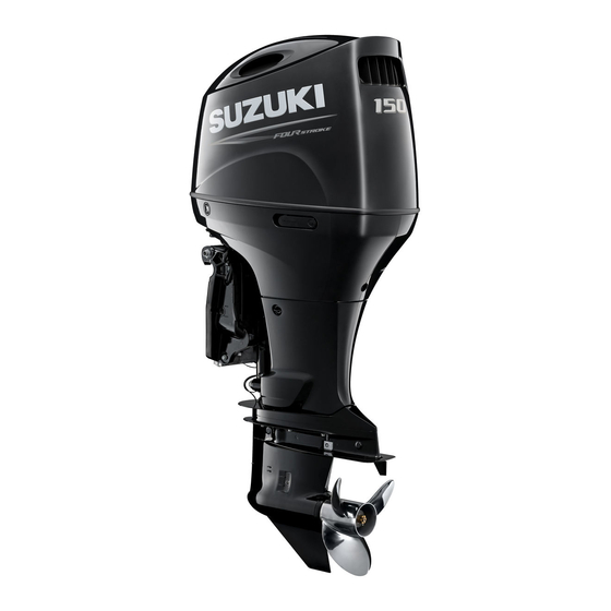
Summary of Contents for Suzuki DF150AP
- Page 1 DF150AP DF175AP DF200AP OWNER’S MANUAL ENGLISH...
- Page 2 California Proposition 65 Warning NOTE: Indicates special instructions to make mainte- WARNING nance easier or instructions clearer. BREAK-IN INFORMATION Operating, servicing and maintain- FOR YOUR OUTBOARD MOTOR ing an outboard motor can expose The first 10 hours are the most important in the you to chemicals including engine life of your engine.
- Page 3 Suzuki and review the manual from safety and emergency equipment. time to time. It contains important infor- • Do not hold onto the motor cover or...
-
Page 4: Table Of Contents
800-336-BOAT (2628). REPLACEMENT ......... Your state’s department of boating and your SETTING AND/OR CHANGING Suzuki Marine dealer can supply you with addi- THE PASSCODE ........ tional information on boating safety and regula- PASSCODE CONFIRMATION.... tions, or you can call the U.S. Coast Guard... - Page 5 ALARM..........OPERATION ......... 57 MAIN SWITCH (OPTION) ....CAUTION SYSTEM ......38 CONTROL PANEL (OPTION)..... INDICATOR CHECK ......BEFORE ATTEMPTING TO START OVER-REVOLUTION CAUTION THE ENGINE........SYSTEM ..........STARTING THE ENGINE ....OIL PRESSURE CAUTION EMERGENCY START......SYSTEM ..........SHIFTING AND SPEED CONTROL ... COOLING WATER CAUTION STOPPING THE ENGINE ....
-
Page 6: Fuel And Oil
GASOLINE in your outboard motor if the ethanol content is Suzuki highly recommends that you use alco- not greater than 10%. hol-free unleaded gasoline whenever possible, with a minimum pump octane rating of 87 Fuel Pump Labeling ((R+M)/2 method). -
Page 7: Engine Oil
Always select • Do not fill the fuel tank all the way to good quality engine oil. Suzuki recommends the use of SAE 10W-40 or the top or fuel may overflow when it 10W-30 SUZUKI MARINE 4-CYCLE ENGINE expands due to heating by the sun. -
Page 8: Location Of Safety Labels
LOCATION OF SAFETY LABELS Read and follow all of the labels on your out- Keep the labels on your outboard motor or fuel board motor or fuel tank. Make sure you under- tank. Do not remove them for any reason. stand all of the labels. -
Page 9: Location Of Parts
LOCATION OF PARTS Power trim and tilt Motor cover (P.T.T.) switch Pilot water hole Flush plug Engine oil drain plug Clamp bracket Anode Manual Anode Anti-cavitation release screw plate Anode Air vent hole plug Trim tab Gear oil level plug Gear oil drain plug Water intake hole Flush plug (No.2) - Page 10 MULTI-FUNCTION GAUGE KEY-FOB PRIMING BULB (Option) (IF EQUIPPED WITH KEYLESS START SYSTEM) Shift lock button Power trim and tilt (P.T.T.) switch Remote control handle Type A Type B REMOTE CONTROL BOX (Option)
-
Page 11: Motor Installation
Suzuki marine dealer. He has the tools, described in 40 CFR 1068.105. the facilities, and the know-how to do the job correctly. -
Page 12: Battery Installation
Counter select connector iliary battery or batteries be installed. Consult your Suzuki dealer for proper battery installa- tion information. • Dual-purpose (Cranking/Deep-cycle) batter- ies can be used if they meet the minimum specifications listed above (MCA, CCA, or RC). -
Page 13: Battery Installation
• When connecting batteries, hexagon-nuts must be used to secure battery leads to bat- Suzuki recommends that you install the termi- tery posts. nal cap on the positive battery terminal to pre- vent an accidental short circuit of battery To hook up the battery, first connect the red terminals. -
Page 14: Sub Battery Cable
The amount of power (12V DC) available for accessories depends on the operating condi- tion of the motor. For detail information, please The electrical system or its components contact an authorized Suzuki Marine Dealer. may be damaged if proper battery pre- cautions are not followed. NOTE: Use of too much power for electrical accesso- •... -
Page 15: Suzuki Keyless Start System (If Equipped With Keyless Start System)
Two (2) key-fobs are supplied with the Keyless Start System. Keyless control unit NOTE: Please consult with a Suzuki Marine Dealer for the installation of the Keyless Start System. Also refer to the “Keyless Start System Instruc- tion Manual” supplied with the product for detailed operating instructions. - Page 16 WARNING NOTICE The key-fob emits radio waves that may The key-fob is comprised of sophisti- interfere with aircraft operations. cated electronic components that can become damaged and may fail to func- tion properly if you do not take proper Do NOT operate the buttons on the key- precaution.
-
Page 17: Key-Fob Battery Replacement
• If the key-fob and the emergency key are lost, immediately contact your authorized Suzuki Marine Dealer. • The key-fob uses a weak radio wave that is susceptible to external influences when it communicates with the keyless control unit. - Page 18 2. Remove the O-ring 1. NOTICE To prevent damage to the key-fob, be careful when replacing the battery. • Install the lithium disc-type battery with the electrodes facing the proper direc- tion. • Do NOT touch the internal circuit of the key-fob when replacing the battery.
-
Page 19: Setting And/Or Changing The Passcode
SETTING AND/OR CHANGING THE PASS- 4. Replace the battery so its + terminal faces CODE the cover side as shown in the illustration. Lithium disc type battery: CR2025 or equiva- By setting a 4-digit passcode, the engine can lent. be started by entering the passcode even if the Confirm that the O-ring is placed in position key-fob battery has run down or the key-fob is on the body side. - Page 20 6. Pull out the emergency stop switch lock (2) Within 60 seconds after performing Step (1), plate. turn the main switch to the “ ” position and then release it. The main switch automati- cally returns to the “ ” position. The buzzer starts emitting short sounds.
- Page 21 NOTE: NOTE: The buzzer emits one (1) short sound for the When performing the passcode input operation 1st digit, two (2) short sounds for the 2nd digit, again after the operation has been cancelled three (3) short sounds for the 3rd digit, and four due to passcode input failure or after having (4) short sounds for the 4th digit.
-
Page 22: Passcode Confirmation
PASSCODE CONFIRMATION 1. Confirm that the engine is stopped. Hold it for five (5) seconds. 2. Make sure the emergency switch lock plate is in place. 3. Confirm the key-fob is within the communi- cation range of the Keyless Start System. 4. -
Page 23: Propeller Selection And Installation
Install a right hand rotation propeller with regular rotation lower unit, or left hand rota- tion propeller with counter rotation lower unit. Please contact your authorized Suzuki Marine Dealer for more detail. Counter rotation lower unit 3. The propeller type suitable for the lower unit... -
Page 24: Propeller Selection
× r/min. (min –1 Left hand propeller: If the engine speed is not within this range, con- sult your authorized Suzuki Marine Dealer to × × × determine which propeller size is best for you. If you change propellers, be sure to perform the... -
Page 25: Propeller Installation
• Trim angle too small (Boat tends to “plow”) • Trim angle too large (Boat tends to “porpoise”) 1. Coat the propeller shaft splines 1 liberally with Suzuki water resistant grease to help prevent corrosion. 2. Place the stopper 2 on the shaft. -
Page 26: Trim Tab Adjustment
NOTICE If you operate the boat with the motor trimmed beyond the maximum trim posi- tion, the water intake holes may be above the water line, causing severe engine damage due to overheating. Tilt range Never operate the boat with the motor trimmed beyond the maximum trim posi- Trim range tion. -
Page 27: Control Handle Adjustment
Adjustable item Friction and detent force Friction IDLE SPEED ADJUSTMENT The idle speed has been factory adjusted between 600 – 700 r/min. in neutral. NOTE: If idle speed cannot be set within the specified range, contact your authorized Suzuki Marine Dealer. -
Page 28: Motor Cover Fastening Adjustment
Motor cover NOTE: There is information that cannot be displayed depending on the model and equipment. NOTE: Consult your authorized Suzuki marine dealer for setting up the multi-function gauge. NOTE: For details the proper handling of the multi- function gauge, refer “OPERATION... -
Page 29: Button Functions
BUTTON FUNCTIONS SCREEN SELECTION The multi-function gauge has four buttons: The multi-function gauge can select the display [MENU], [ ], [ ], and [SET]. screen from the following choices. • Engine Speed • Ground Speed/Fuel Information • Fuel Information • All Items Display Screen (Full Item) To select the display screen: Press the [SET] button and select the desired display screen. - Page 30 1. Engine Speed Display Screen 3. Fuel Information Display Screen The engine speed 1, shift position 2, trim This screen indicates the remaining fuel lev- position 3, time 4, engine position 5 and els of each tank installed, along with sub sub information 6 are displayed.
-
Page 31: Sub Information Selection
SUB INFORMATION SELECTION 4. All Items Display Screen When the Engine Speed, Ground Speed/Fuel This screen displays all the general indica- Information or Fuel Information screen is dis- tion items for this gauge. played, press the [ ] or [ ] button to switch This screen can be selected between digital, the sub Information display in the following... - Page 32 1. Total Operating Hours 5. Instantaneous fuel flow The total operating hours from brand-new This screen indicates the instantaneous fuel engine are displayed. flow of each outboard motor. 2. Trip Time 6. Total Instantaneous fuel flow This screen indicates the trip time since it This screen indicates the total instantaneous was reset last time.
-
Page 33: Menu Information Selection
MENU INFORMATION SELECTION 9. Total fuel used The menu screen is displayed when the MENU This screen indicates the total fuel used of button is pressed while any screen is displayed. all outboard motors installed. While the menu screen is displayed, press the MENU button to return to the previous screen. - Page 34 Day or Night Press the [ ] or [ ] button to select “Day or Night” and press the [SET] button. Next, select “Day” or “Night” using the [ ] or [ ] button and then press the [SET] button. Day or Night Night Sync...
- Page 35 Data Output NOTE: For details the proper handling of the multi- function gauge, refer “OPERATION INSTRUCTION MANUAL” packed in the gauge. Press the [ ] or [ ] button to select “Data Output” and then press the [SET] button to dis- play the Data Output selection menu.
- Page 36 5. Initial Setting Quantity: set the unit for fuel quantity. Items in the Initial Setting include important Press the [SET] button to select the unit. items for initial setting. Therefore, the confirma- tion screen “Revise initial setting?” is displayed when you select “Initial Setting” in the menu screen and press the [SET] button.
- Page 37 12h or 24h: select 12-hour or 24-hour display. Setting for the gauge and engine position. Press the [SET] button to select “12h” or “24h.” Consult your authorized Suzuki marine dealer for setting change of “Position”. Sensor Setting Settings for various sensors.
-
Page 38: Alarm
If the Caution System activates while you are operating your outboard motor, stop the motor as soon as possible and cor- rect the problem or consult your autho- rized Suzuki marine dealer assistance. -
Page 39: Indicator Check
Consult your authorized Suzuki marine This system must be reset by moving the throt- dealer. -
Page 40: Oil Pressure Caution System
Check the oil level and add oil if necessary. If Revolution Caution System. the oil level is correct, consult your authorized Suzuki Marine Dealer. Consult your authorized Suzuki marine dealer if the Over-Revolution Caution NOTICE System activates for no apparent reason. -
Page 41: Cooling Water Caution System
If this system activates, the “Overheat” and cau- mally. If either of the above situations arises, tion alarm icon are displayed on screen, and your authorized Suzuki Marine Dealer must be the buzzer sounds. In addition, when this sys- consulted as soon as possible. -
Page 42: Battery Voltage Caution System
The “Low Battery Voltage” indication clears boat accessories, contact your authorized when any of the button is pressed in the gauge. Suzuki Marine Dealer. However, the caution alarm icon is displayed until eliminating the cause. This system will be canceled automatically when the battery voltage restores to the proper voltage level. -
Page 43: Electronic Throttle And Shift Control Caution System
If this system activates for no apparent SYSTEM reason, there may be a problem with the system. CONTROL UNIT COMMUNICATION Consult your authorized Suzuki marine CAUTION SYSTEM dealer. This system is activated in the event of an error in the control system of the electronic throttle and shift systems. -
Page 44: Throttle System Caution System
If this system activates for no apparent reason, there may be a problem with the system. Consult your authorized Suzuki marine dealer. THROTTLE SYSTEM CAUTION SYSTEM This system is activated in the event of an error of the control system of the electronic throttle. -
Page 45: Gauge Communication Caution System
If this system activates, the “Check Station Set- If this system activates for no apparent ting” is displayed on screen. reason, there may be a problem with the system. Consult your authorized Suzuki marine dealer. GAUGE COMMUNICATION CAUTION SYSTEM This system activates when there is a commu- nication error of the gauge. -
Page 46: Troll Condition Caution System
– The correct key-fob has been authenti- cated by the Keyless Start System. • If this caution system activates continuously, consult your authorized Suzuki Maine Dealer. The “Check Troll System” indication clears when any of the button is pressed in the gauge. -
Page 47: Key-Fob Battery Caution System
• If the message “Keyless Unit Battery Low” is displayed, check the following: – The 12 volt battery is in sound condition. – Contact failure of the battery terminal. • If this caution system activates continuously, consult your authorized Suzuki Maine Dealer. -
Page 48: Diagnostic System
X” and check engine icon are displayed on screen, and the buzzer sounds. Consult your authorized Suzuki marine dealer for repair of the control system. The “Check Engine X – X” is cleared when any of the buttons are pressed in the gauge. -
Page 49: Oil Change Reminder System
CANCELLATION OIL CHANGE REMINDER 1. If equipped with Keyless Start System: SYSTEM Turn the Keyless Start System to ON state by turn the main switch to the “ ” position This system informs the operator of the time for and then release it. The main switch auto- replacing engine oil on the basis of the mainte- matically returns to the “... -
Page 50: Engine Stalling Caution System
The “Water in Fuel” indication clears when any has been replaced. Once the system has of the button is pressed in the gauge. However, operated, however, Suzuki strongly recom- the caution alarm icon is displayed until the mends that the engine oil be replaced before eliminating the cause. -
Page 51: Operation Of Tilting Systems
SYSTEMS do so, and check the fuel filter/water separator for water. Or consult your authorized Suzuki POWER TRIM AND TILT marine dealer. The “Power Trim and Tilt” is operated by press- ing the switch. -
Page 52: Tilt Limiter Cam
If not equipped with Keyless Start System: 3. To check your adjustment, tilt the motor fully up to check for motor contact. WARNING Adjust further if necessary. Return the motor to the normal running posi- tion for each adjustment, and repeat your The power trim and tilt (PTT) switch on check after each adjustment. -
Page 53: Tilt Lever
4. Continue to operate the Power Trim and Tilt CAUTION “DOWN” switch until the trim rods are com- pletely retracted. The motor is very heavy. When you tilt it manually, you could injure your back or slip and fall causing injury. When you tilt the motor manually, ensure that your grip and footing are secure and that you are able to support the weight of... -
Page 54: Inspection Before Boating
INSPECTION BEFORE If not equipped with Keyless Start System: BOATING CAUTION WARNING The remote Power Trim and Tilt switch will work when the main switch is off. If Failure to inspect your boat and motor someone activates the switch while you before beginning a trip can be hazardous. - Page 55 1. Place the motor in a vertical position, 3. Insert the dipstick all the way into the then remove the motor cover 1 by engine, then remove it again. unlocking the lever 2 and 3. UPPER LIMIT LOWER LIMIT The oil on the dipstick should be between 2.
-
Page 56: Break-In
BREAK-IN • Check the battery solution level. The level should be kept between the MAX and the MIN level lines at all times. If the Proper operation during this break-in period will level drops below the MIN level line, refer help ensure maximum life and performance to MAINTENANCE section. -
Page 57: Operation
OPERATION 2. For the next 1 hour: Safe boating conditions permitting, operate the engine in gear at 4000 r/min. or at three- MAIN SWITCH (OPTION) quarter throttle. Avoid running the engine at If equipped with Keyless Start System: full throttle. Turn the Keyless Start System to ON or OFF 3. -
Page 58: Control Panel (Option)
Start & Stop Switch This is a switch to start and stop the engine. The engine can be started with the remote con- trol handle at the neutral position. CONTROL PANEL (OPTION) Station Select Switch This switch control between driving stations on boats equipped with more than one driving sta- tion. - Page 59 If it is not possible to out the THROTTLE switch then turn ON it after 20 seconds past. ONLY mode, turn OFF the main switch then • Consult your authorized Suzuki marine turn ON it after 20 seconds past. dealer if the station can not be selected.
- Page 60 NOTE: NOTE: • If equipped with Keyless Start System: • If equipped with Keyless Start System: When the Keyless Start System has been When the Keyless Start System has been turned to ON state, synchronization is auto- turned to ON state by operating the main matically selected.
-
Page 61: Before Attempting To Start The Engine
BEFORE ATTEMPTING TO START THE ENGINE 1. Lower the motor into the water. 2. Make sure that the motor fuel hose and the hose from the boat’s fuel tank are securely attached and clamped. 3. Make sure the motor is in “NEUTRAL”. 4. -
Page 62: Starting The Engine
STARTING THE ENGINE WARNING Exhaust gas contains carbon monoxide, a dangerous gas that is difficult to detect because it is colorless and odorless. Breathing carbon monoxide can cause death or severe injury. Never start the engine or let it run indoors or where there is little or no ventilation. - Page 63 3. Push the start & stop switch to start the engine. NOTE: By pressing the Start & Stop switch once, the starter motor turns for 3 seconds continuously until the engine starts. If not equipped with Keyless Start System: Turn the main switch to the “ON” position. NOTICE If you hold in the START &...
- Page 64 If you notice that water does Before starting off, check to make sure not spray out of the pilot water hole, stop the that the emergency stop switch operates engine as soon as possible and consult your properly. authorized Suzuki Marine Dealer.
-
Page 65: Emergency Start
3. Make sure lock plate 3 is in position. If equipped with Keyless Start System: EMERGENCY START NOTE: One (1) emergency key is included in the main switch panel for the Keyless Start System. If the key-fob is lost or the key-fob battery has run low, the Keyless Start System OFF (locked) state can be released by using the emergency key and entering the 4-digit passcode. - Page 66 6. Turn the emergency key 2 to the “ ” posi- (2) The buzzer starts emitting short sounds. tion and hold it until the buzzer sounds. When the buzzer sounds for the same num- Turn the emergency key back to the “ ”...
- Page 67 NOTE: (4) Turn the emergency key to the counterclock- The buzzer emits one (1) short sound for the wise within 10 seconds after entering the 4th 1st digit, two (2) short sounds for the 2nd digit, digit of the passcode. The buzzer emits two three (3) short sounds for the 3rd digit, and four (2) short sounds when the passcode input is (4) short sounds for the 4th digit.
- Page 68 To start the engine: To stop the engine: (5) Install the lock plate 3 on the emergency 1. Shift into “NEUTRAL”. stop switch. 2. After operating at full throttle, cool off the engine a few minutes by allowing it to idle or troll at low speed.
-
Page 69: Shifting And Speed Control
2. • When the engine stops, the clutch moves to A detent or notch is present on all Suzuki con- the neutral position irrespective of the posi- trol boxes to provide a “feel” for positions A, B, tion of the remote control lever. -
Page 70: Stopping The Engine
Speed control 4. Turn the Keyless Start System to OFF To increase speed after you have shifted into (locked) status by one of the following meth- gear, continue moving the control handle for- ods. ward or rearward. • Make sure that the key-fob is within the communication range of the keyless con- ... - Page 71 If not equipped with Keyless Start System: NOTICE To stop the engine: 1. Shift into “NEUTRAL”. 2. After operating at full throttle, cool off the If the Keyless Start System is in ON state engine a few minutes by allowing it to idle or while the engine is not running, the bat- troll at low speed.
-
Page 72: Mooring
MOORING WARNING The motor should be tilted up out of the water when you moor the boat in shallow water or if the motor will not be used for some time, to pro- Unauthorized use of your boat could lead tect it from damage by underwater obstacles at to an accident or damage to your boat. -
Page 73: Operation In Shallow Water
Power Trim and Tilt switch. ] or [ ] button. WARNING NOTE: Please contact your authorized Suzuki Marine Dealer for more information. When the motor is beyond the maximum Setting the Troll Mode trim position, the swivel bracket will not 1. - Page 74 Example of the troll mode display on the Multi- Function Gauge that can operate the troll mode. • This icon appears on the screen of the Multi-Function Gauge that was operated to get into the troll mode, and Example of the troll mode display on the Multi- shows operatable Multi-Func- Function Gauge that cannot operate the troll tion Gauge of the troll mode.
- Page 75 [UP] button or [DN] switch. beep sounds engine speed increases by 50 r/min. • When pressing the [ ] button, one short beep sounds engine speed decreases by 50 r/min. Troll mode switch NOTE: Please contact your authorized Suzuki Marine Dealer for more information.
-
Page 76: Operation In Salt Water
Setting the Troll Mode Adjusting Trolling Speed 1. Shift into forward or reverse gear and make • When pressing the “UP” switch, one short sure that the throttle is fully closed (in-gear beep sounds engine speed idle speed). increases by 50 r/min. 2. -
Page 77: Operation In Freezing Weather
If it is necessary to remove the outboard motor drains completely. from your boat, we recommend that you ask your authorized Suzuki Marine Dealer to do the work for you. NOTICE If you leave your outboard motor out of... - Page 78 Horizontal transport: NOTICE 1. Drain the engine oil. Refer to the ENGINE OIL section. 2. Drain the gasoline from the vapor separator If spilled gasoline is just left on painted as follows: surface, it may cause a stain or discolora- (1) Remove the motor cover.
-
Page 79: Trailering
TRAILERING NOTICE When trailering your boat with the motor attached, keep the motor in the normal operat- If you are not careful when resting the ing position unless there is not enough ground outboard on its side and do not take clearance. -
Page 80: Inspection And Maintenance
INSPECTION AND MAINTENANCE NOTICE judged by number of hours or number of months, whichever comes first. MAINTENANCE, REPLACEMENT REPAIR EMISSION CONTROL WARNING DEVICES AND SYSTEMS MAY BE PER- FORMED BY ANY MARINE SI ENGINE REPAIR ESTABLISHMENT OR INDIVIDUAL Exhaust gas contains carbon monoxide, USING ANY PART WHICH HAS BEEN a dangerous gas that is difficult to detect CERTIFIED UNDER THE PROVISIONS IN... -
Page 81: Tool Kit
Suzuki strongly recom- instructions in this section if you have mends that you use genuine Suzuki parts mechanical experience. If you are not or their equivalent. sure whether you can successfully com-... -
Page 82: Spark Plug
(usually evidenced by black- ening of the insulator or a wet electrode), per- formance may suffer. Ask your authorized Suzuki Marine dealer to evaluate either of these problems to determine the cause. SPARK PLUG Remove the spark plugs as follows: 1. - Page 83 To maintain a strong spark, you should clean NOTICE and adjust the plug at the interval shown in the maintenance schedule. Remove carbon deposits from the spark plug Use of improper spark plugs or improp- using a small wire brush or spark plug cleaner, erly tightening spark plugs can cause and adjust the gap as follows: severe engine damage.
-
Page 84: Breather And Fuel Line
Fuel leakage can contribute to an explo- they must be replaced. Consult your authorized sion or fire, resulting in serious personal Suzuki Marine dealer if it is necessary to injury. replace them. Have your authorized Suzuki marine... -
Page 85: Engine Oil
ENGINE OIL 3. Place a drain pan under the engine oil drain screw. WARNING CAUTION Never perform any ENGINE OIL proce- dure with the motor running, as serious The engine oil temperature may be high injury can occur. enough to burn your fingers when the drain plug is loosened. -
Page 86: Gear Oil
GEAR OIL 7. Check the engine oil level. To check the gear oil level, adjust the engine to an upright position, remove the gear oil level plug 1 and look into the hole. The oil level should be at the bottom edge of the hole. If the oil level is low, add the specified gear oil until the level reaches the bottom edge of the hole. -
Page 87: Low Pressure Fuel Filter
Clean the magnet if there is a metal powder on taminated with water. Immediately con- Do not make a mistake in their positions when tact your authorized Suzuki marine dealer install them. for advice. Do not operate your outboard until the oil is changed and the cause of 4. - Page 88 Inspect and clean the fuel filter as follows: NOTICE 1. Turn the engine off and allow it to cool. 2. If equipped with Keyless Start System: Improperly loosening the filter cup can Make sure that the keyless start system is in cause sensor lead wire damage.
-
Page 89: Lubrication
15. Restart the engine and check that there are no leaks around the fuel filter. NOTE: If any water exists in the fuel filter cup, remove the cup and drain the water. Always dispose of excess fuel safely. For questions, consult your authorized Suzuki marine dealer. - Page 90 NOTE: If grease will not inject into the fitting, consult your Authorized Suzuki Marine Dealer. Engine holder Your authorized Suzuki Marine Dealer may also have additional recommendations due to NOTE: regional climate or operating conditions. Before applying grease through the steering Please consult him for advice.
-
Page 91: Corrosion Prevention
• Do not paint anodes, as this will render sion measures may be helpful under those con- them ineffective. ditions. Consult your authorized Suzuki Marine • Periodically clean anodes with a wire Dealer for details. brush to remove any coating which might decrease their protective ability. -
Page 92: Bonding Wires
BATTERY BONDING WIRES If you are using a maintenance-free battery, Bonding wires are used to electrically connect inspect the window area according to the the engine components so they exist in a com- instructions on the battery to make sure the bat- mon ground circuit. -
Page 93: Engine Oil Filter
ENGINE RUNNING – Vertical position – procedures. Suzuki recommends that you flush the water passage by using this method. ENGINE OIL FILTER To flush the water passages, you must obtain a The engine oil filter must be changed by autho- commercially available engine flush device. - Page 94 NOTICE Severe engine damage can occur in as lit- tle as 15 seconds if the engine is started without supplying water to the cooling system. Never start the motor without supplying water to the cooling system. 1. Make sure that the motor is stopped. 2.
- Page 95 ENGINE NOT RUNNING – Vertical position – 3. Install garden hose directly or by using a 1. Make sure that the motor is stopped. hose connector matched to flushing point 2. Remove one of the plug A or C from the thread B.
-
Page 96: Submerged Motor
2. Remove the motor cover and immediately 7. Have your authorized Suzuki marine dealer wash the engine thoroughly with fresh water inspect the engine as soon as possible. to completely remove all salt, mud, and sea- weed. -
Page 97: Storage Procedure
After washing, the water remaining son), it is recommended that you take your on the engine should be wiped off with dry motor to your authorized Suzuki Marine Dealer. clothes. However, if you choose to prepare the motor for... -
Page 98: Battery Storage
BATTERY STORAGE AFTER STORAGE 1. When the outboard motor will not be used for a month or longer, remove the battery When taking your motor out of storage, follow and store it in a cool, dark place. Do not set the procedure below to return it to operating battery on concrete or earth, as this will condition:... -
Page 99: Emission Control Information
Such damage may not be cov- ered under warranty. If you are not sure about the proper action to correct a problem, consult your EMISSION CONTROL Suzuki marine dealer. INFORMATION Starter motor will not operate: • Emergency stop switch lock plate is not in NOTICE position. - Page 100 Engine idles unstably or stalls: Engine vibrates excessively: • Spark plug is fouled. • Propeller is damaged. • Fuel hose is kinked or pinched. • Engine mounting bolts or clamp screws are • Fuel hose is not properly connected to loose.
- Page 101 FUSE 4. Remove the Sub battery cable fuse. 1. If equipped with Keyless Start System: Turn the Keyless Start System to OFF state. If not equipped with Keyless Start System: Turn the main switch to the “off” position. 2. Remove the motor cover. 3.
- Page 102 Spare fuses 9, 0 and A are provided for the If a new fuse blows in a short time after back of fuse box cover. installation, you may have a major electri- cal system problem. Consult your SUZUKI marine dealer. Fuse box cover...
-
Page 103: Specifications
SPECIFICATIONS Item DF150AP DF175AP DF200AP Engine Type 4 Stroke Number of Cylinders Bore and Stroke 97.0 × 97.0 mm (3.81 × 3.81 in.) Piston Displacement 2867 cm (174.9 cu. in.) Maximum output 110.3 kW (150PS) 128.7 kW (175PS) 147.0 kW (200PS) Full Throttle Operating Range 5000 –... - Page 104 WIRING DIAGRAM DF150AP/175AP/200AP...
- Page 105 Equipped with Keyless Start System...
- Page 106 Not equipped with Keyless Start System...
- Page 107 Prepared by June, 2019 Part No. 99011-96LD0-03B Printed in Japan © COPYRIGHT SUZUKI MOTOR CORPORATION 2019...
Need help?
Do you have a question about the DF150AP and is the answer not in the manual?
Questions and answers