
Subscribe to Our Youtube Channel
Related Manuals for LINDR KONTAKT 300/K


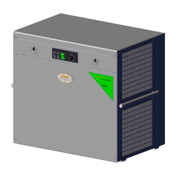
Summary of Contents for LINDR KONTAKT 300/K
- Page 1 INSTRUCTION MANUAL LINDR FLOW-THROUGH CONTACT COOLING ENGLISH Number 009-2020 REV00 Valid 2020-03-09 KONTAKT 300/K TWIN POWER GREEN LINE KONTAKT 300 TWIN POWER GREEN LINE...
- Page 2 Sadová 132 503 15 Nechanice, Czech Republic mob.: + 420 775 715 494 tel. : +420 495 447 239 e-mail: info@lindr.cz web: www.lindr.cz, www.lindr.eu SYMBOLS AND MARKINGS USED IN THE MANUAL: WARNING: NOTE: Not following instructions may cause injury or This symbol indicates information and recom- damage the device.
-
Page 3: Table Of Contents
Contents: Introduction ........Description of the cooler ........Machine plate .. -
Page 4: Introduction
The time needed to accumulate pliance and familiarised with potential dan- energy is ca. 10 min. Lindr cooling technol- gers. ogy has 45 % higher output than is its input WARNING: Children must not be allowed energy. -
Page 5: Installation And Placement
WARNING: Never place tools or other ob- WARNING: After unpacking, place the cool- ject into the fan. er so that heat created by the cooling unit can be vented sufficiently. WARNING: Never touch electrical compo- WARNING: Do not place objects that could nents with wet or damp hands. -
Page 6: Electrical Connection
9. DESCRIPTION OF THE COOLER: Pressure gauge 10. Advert panel illumination switch (ONLY FOR TYPE KONTAKT 300/K) Pressure regulation 11. Air compressor switch (ONLY FOR TYPE KONTAKT 300/K) (ONLY FOR TYPE KONTAKT 300/K) Air outlet –... -
Page 8: Tap Installation
10. TAP INSTALLATION: figure figure VYR 02359 Spacer ring 5/8“ SPO 02216 Seal NOTE: The tap is not included 11. KEG COUPLER ASSEMBLY 11.1 Outlet for Keg Pressurisation Variant of connection with the use of a bushing; the hose is fitted onto the bushing and affixed with a clip. - Page 9 figure figure figure figure CHECK VALVE WARNING: Before you screw the rapid coupling onto the 5/8“ thread, make sure the keg coupler (air inlet for delivery medium) has a lip valve (check valve) fitted on it. 11.2 Outlet for Beverage Screw an F 5/8“...
-
Page 10: Beverage Supply Connection And Pressurisation
12. BEVERAGE SUPPLY CONNECTION AND PRESSURISATION: 1. Interconnect the cooler with the keg cou- 2. Interconnect the cooler with the keg cou- pler by connecting a beverage tube onto the pler by connecting an air tube onto the thread on the left side of the cooler marked as AIR . thread on the left side of the cooler marked as INLET 1 . - Page 11 11 a obrázek Drink Drink NOTE: The figure shows a model connection example; for other connection options, consult a specialised company or the manufacturer.
-
Page 12: Inlet And Outlet Marking
13. INLET AND OUTLET MARKING: 12 a figure 12 b figure 12 c figure Outlet 2 Outlet 1... -
Page 13: Built-In Air Compressor
14. BUILT-IN AIR COMPRESSOR: 13 a figure (ONLY FOR TYPE KONTAKT 300/K) The air compressor is built into the cooling device itself. The compressor can be turned off sepa- rately with a switch. Air pressure is controlled automatically. Output pressure can be set in 1-4 bar range using a regulator knob. -
Page 14: Thermostat Placement
16. THERMOSTAT PLACEMENT: 14 A figure The mechanical thermostat with 1 -7 numeri- cal scale located on the front of the cooler. 17. TEMPERATURE AND ADJUSTMENT: TThe temperature of the cooled beverage is controlled by a mechanical thermostat in temperature range of 2 °C to 8 °C. 14 b 14 c 14 d... -
Page 15: Keg Tapping And Untapping
18. KEG TAPPING AND UNTAPPING: WARNING: Make sure the 18.1 Keg Tapping: Procedure for tapping a keg using an S system keg coupler: adapter is clean before tapping the keg! S system keg coupler 15 A 15 b figure figure 15 c 15 d figure... - Page 16 18.2 Keg Untapping: Procedure for untapping a keg using an S system keg coupler: 16 a 16 b figure figure 16 c figure 18.3 Keg Tapping: Procedure for tapping a keg using an A system keg coupler: WARNING: Make sure the adapter is clean before tapping A system keg the keg!
-
Page 17: Putting Into Operation
17 a 17 b figure figure 18.4 Keg Untapping: Procedure for untapping a keg using an A system keg coupler: 17 c 17 d figure figure 19. PUTTING INTO OPERATION 1. Connect the air and beverage tubing according to point 12. 2. -
Page 18: Maintenance
20. MAINTENANCE: 14 days by a person with chemical Flush the beverage tubing of the cooler after engineering qualifications. The condenser each use with pressurised water (see Sanita- must be checked for cleanliness every month. tion by Water). To make flushing easier, use a Any dirt found must be cleaned with com- sanitation adapter according to your type of pressed air or wiped off. -
Page 19: Cleaning The Condenser
24. CLEANING THE CONDENSER: The condenser must be cleaned with compressed air 1x a month. 19 A 19 b figure figure 25. SANITATION BY WATER: (sanitation adapter) Connect the sanitation adapter (not included) to water mains using a hose. WARNING! Maximum water temperature must not exceed 25 °C. 19 c 19 d figure... -
Page 20: Changing The Illuminated Advertising Panel
26. CHANGING THE ILLUMINATED ADVERTISING PANEL: The advertising panel can be changed on customer request. 20 a figure WARNING: Tighten the screws fastening the plexiglass gently. Maximum torque is 0.20 Nm. 5. Insert a new advertisement placard Instructions for Replacement 6. - Page 21 21 a figure...
-
Page 22: Table Of Malfunctions
27. TABLE OF MALFUNCTIONS: Malfunction Cause Removal beverage does not flow keg tapped incorrectly check that the keg coupler lever is pushed down device with built-in compressor - turn on the switch water from sanitation froze turn off the device; then wait until the beverage starts flowing again (may take a few minutes, or hours!) compensator is closed move the compensator lever... -
Page 23: Spare Parts
When ordering spare parts, always provide the following: • product type • production year • product's serial number • full name of the spare part and its number 29. TECHNICAL DATA Kontakt 300/K Twin Power Kontakt 300 Twin Power Name Green Line Green Line Power...
Need help?
Do you have a question about the KONTAKT 300/K and is the answer not in the manual?
Questions and answers