Advertisement
Quick Links
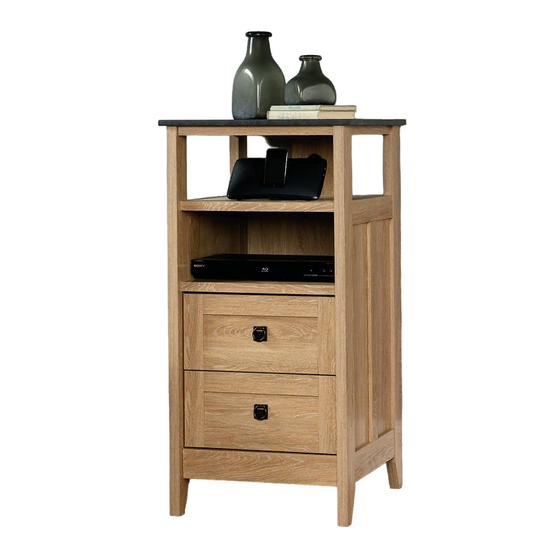
412321
Technology Pier
August Hill Collection
PLEASE CONTACT US
BEFORE RETURNING
YOUR UNIT TO THE STORE
1-800-523-3987
www.sauder.com
NOTE: THIS INSTRUCTION BOOKLET CONTAINS
IMPORTANT SAFETY INFORMATION.
PLEASE READ AND KEEP FOR FUTURE REFERENCE.
English .................... Page 1-22
Français ...............Pages 23-25
Made in the USA
Espanol .............Páginas 26-29
Archbold, OH
Lot #: 353030
Date Purchased: ____________________
05 / 08 / 13
Advertisement

Related Manuals for Sauder 412321


Summary of Contents for Sauder 412321
- Page 1 412321 Technology Pier August Hill Collection NOTE: THIS INSTRUCTION BOOKLET CONTAINS IMPORTANT SAFETY INFORMATION. PLEASE CONTACT US PLEASE READ AND KEEP FOR FUTURE REFERENCE. BEFORE RETURNING English ....Page 1-22 YOUR UNIT TO THE STORE Français ....Pages 23-25 Made in the USA 1-800-523-3987 Espanol .....Páginas 26-29...
- Page 2 TABLE OF CONTENTS ASSEMBLY TOOLS REQUIRED Part Identifi cation .......3 No. 2 Phillips Screwdriver Hardware Identifi cation .....4 Tip Shown Actual Size Assembly Steps ....5-22 Français ......23-25 Hammer Espanol ....... 26-29 Safety ........30 Warranty ........31 Page 2 www.sauder.com/services 412321...
-
Page 3: Part Identification
REAR LEG LONG TOP MOLDING DRAWER FRONT BOTTOM LOWER END MOLDING RIGHT DRAWER SIDE SHELF UPPER END MOLDING LEFT DRAWER SIDE SMALL BACK SHELF MOLDING D962 DRAWER BOTTOM LARGE BACK SHORT TOP MOLDING DRAWER BACK D962 D962 412321 www.sauder.com/services Page 3... -
Page 4: Hardware Identification
BLACK 9/16" LARGE HEAD SCREW - 12 GOLD 5/16" FLAT HEAD SCREW - 16 SILVER 1/4" MACHINE SCREW - 2 NAIL - 29 Screws are shown actual size. You may receive extra hardware with your unit. Page 4 www.sauder.com/services 412321... - Page 5 Assemble your unit on a carpeted fl oor or on the empty carton to avoid scratching your unit or the fl oor. ® To begin assembly, push a SAUDER TWIST-LOCK FASTENER (X) into the large holes in the BOTTOM (D), SHELVES (E), and SMALL BACK (F).
- Page 6 Arrow (16 used) Arrow Arrow Arrow Turn sixteen CAM SCREWS (Z) into the TOP (C) and LEGS (H and I). Push sixteen HIDDEN CAMS (Y) into the ENDS (A and B) and LEGS (H and I). Page 6 www.sauder.com/services 412321...
- Page 7 Tighten Arrow Risk of damage or injury. Hidden Cams must be completely Arrow Maximum tightened. Hidden 210 degrees Cams that are not completely tightened Minimum may loosen, and parts 190 degrees may separate. To completely tighten: 412321 www.sauder.com/services Page 7...
- Page 8 2. Slide the VERTICAL MOLDING (O) onto the ENDS (A and B) until is against the LOWER END MOLDINGS (R). Line up the groove in the MOLDINGS over the head of the SCREWS in the MOLDINGS. Page 8 www.sauder.com/services 412321...
- Page 9 SCREWS and onto the ENDS. Slide the UPPER END MOLDINGS (S) onto the ENDS (A and B) until it is against the LEGS. Line up the groove in the MOLDINGS over the head of the SCREWS in the MOLDINGS. 412321 www.sauder.com/services Page 9...
- Page 10 The HIDDEN CAMS should be here. Carefully flip the ENDS over. Fasten the remaining LEGS (H and I) to the ENDS (A and B). Tighten six HIDDEN CAMS. Page 10 www.sauder.com/services 412321...
- Page 11 Separate the EXTENSION SLIDES (W) from the EXTENSION RAILS (V) as shown in the upper diagram. Be prepared, the parts are greasy. Fasten the EXTENSION RAILS (V) to the ENDS (A and B). Use eight GOLD 5/16" FLAT HEAD SCREWS (MM) through the 1st and 3rd holes from the open end of the SLIDES. 412321 www.sauder.com/services Page 11...
- Page 12 ® How to use the SAUDER TWIST-LOCK FASTENER 1. Insert the dowel end of the FASTENER into the hole of the adjoining part. NOTE: The dowel end of the FASTENER must remain fully inserted in the hole of the adjoining part while locking the FASTENER.
- Page 13 Slide the BOTTOM MOLDING ( P) onto the notched edge of the BOTTOM (D) and the SHELF MOLDINGS (T) onto the notched edges of the SHELVES (E) until they are against the RIGHT END (A). *U.S. Patent No. 5,499,886 412321 www.sauder.com/services Page 13...
- Page 14 Angled edge ® Fasten the LEFT END (B) to the BOTTOM (D) and SHELVES (E). Tighten six TWIST-LOCK FASTENERS. Page 14 Page 14 www.sauder.com/services www.sauder.com/services 412321 412321...
- Page 15 Fasten the TOP (C) to the LEGS (H and I). Tighten four HIDDEN CAMS. ® NOTE: Be sure the TWIST-LOCK FASTENER dowel in the SMALL BACK (F) inserts into the hole in the TOP. You will tighten ® the TWIST-LOCK FASTENER in step 13. 412321 412321 www.sauder.com/services www.sauder.com/services Page 15 Page 15...
- Page 16 Fasten the TOP MOLDINGS (Q and U) to the ANGLE BRACKETS on the TOP (C). The LONG TOP MOLDING (Q) will get fastened near the front edge of the TOP (C). NOTE: There are no holes in the MOLDINGS. The screws will tighten into the groove of the MOLDINGS. Do not over tighten. Page 16 www.sauder.com/services 412321...
- Page 17 NOTE: Perforations have been provided for access through the BACK. Carefully cut out the holes needed. Tighten the TWIST-LOCK ® FASTENER in the SMALL BACK (F). Push two CORD CLIPS (FF) into the holes in the SMALL BACK (F). 412321 www.sauder.com/services Page 17...
- Page 18 2. Slide the DRAWER BOTTOM (D962) into the grooves in the DRAWER SIDES (K and L) and DRAWER FRONT (J). 3. Fasten the DRAWER BACK (D62) to the DRAWER SIDES (D10 and D11). Use four BLACK 1-9/16" FLAT HEAD SCREWS (JJ). Repeat steps 14 and 15 for the remaining drawer. Page 18 www.sauder.com/services 412321...
- Page 19 Fasten the EXTENSION SLIDES (W) to the DRAWER SIDES (D10 and D11). Use four GOLD 5/16" FLAT HEAD SCREWS (MM) through holes #1 and #3. NOTE: The screw head in the CAM must be visible through the slotted hole in the SLIDE. Repeat this step for the remaining drawer. 412321 www.sauder.com/services Page 19...
- Page 20 (2 used for the PULLS) Fasten a PULL (HH) to the DRAWER FRONT (J). Use a SILVER 1/4" MACHINE SCREW (NN) through a WASHER (GG) and into the PULL (HH). Repeat this step for the remaining drawer. Page 20 www.sauder.com/services 412321...
- Page 21 To insert a drawer into your unit, line up the EXTENSION SLIDES on the drawer with the EXTENSION RAILS on the unit and push the drawer into the unit until the drawer is fully inserted. The drawer will push in hard until it is all the way in, then it will slide in and out easier. 412321 www.sauder.com/services Page 21...
- Page 22 Tighten the SCREW when finished with adjustments. NOTE: Please read the back pages of the instruction booklet for important safety information. This completes assembly. To clean your unit, dampen a cloth with tap water and wipe. Page 22 www.sauder.com/services 412321...
-
Page 23: Liste De Pièces
VIS NOIRE TÊTE PLATE 40 mm ..8 pour future référence. MOULURE DE DESSOUS ....1 VIS NOIRE TÊTE PLATE 14 mm ...14 Pour contacter Sauder MOULURE DE DESSUS LONGUE .1 en ce qui concerne cet VIS NOIRE TÊTE LARGE 14 mm ..12 élément, faire référence... - Page 24 ÉTAPE 7 Pour commencer l'assemblage, enfoncer une FIXATION Séparer les COULISSES D'EXTENSION (W) des TWIST-LOCK® SAUDER (X) dans les gros trous du GLISSIÈRES D'EXTENSION (V) comme l'indique le DESSOUS (D), TABLETTES (E) et PETIT ARRIÈRE (F). schéma du haut. Faire attention car les pièces sont graissées.
- Page 25 Ceci complète l'assemblage. Pour nettoyer l’unité, TIROIR (D10 et D11). Utiliser quatre VIS NOIRES TÊTE humidifi er un chiffon avec de l’eau du robinet et essuyer. PLATE 40 mm (JJ). Répéter les étapes 14 et 15 pour l’autre tiroir. 412321 www.sauder.com/services Page 25...
-
Page 26: Lista De Partes
PERDIDA de 40 mm ......8 MOLDURA DE PANEL SUPERIOR en contacto con LARGA ..........1 TORNILLO NEGRO DE CABEZA Sauder en cuanto a PERDIDA de 14 mm ......14 esta unidad, refi érase MOLDURA DE EXTREMO al número de lote y INFERIOR ........2 TORNILLO NEGRO DE CABEZA al número de modelo... - Page 27 B). Apriete seis EXCÉNTRICOS ESCONDIDOS. Para comenzar el ensamblaje, empuje un SUJETADOR TWIST-LOCK® SAUDER (X) dentro de los agujeros PASO 7 grandes del FONDO (D), de los ESTANTES (E) y del DORSO PEQUEÑO (F).
- Page 28 NOTA: Hay perforaciones provistas para el acceso a través del DORSO. Cuidadosamente corte los agujeros necesarios. Apriete el SUJETADOR TWIST-LOCK® del DORSO PEQUEÑO (F). Introduzca girando dos GRAPAS DE CABLE (FF) dentro los agujeros en el DORSO PEQUEÑO (F). Page 28 www.sauder.com/services 412321...
- Page 29 Esto completa el ensamblaje. Para limpiar la unidad, humedezca un paño con agua de llave y limpie. 412321 www.sauder.com/services Page 29...
- Page 30 Además, el peso y la ubicación del tubo de imagen tienden a causar la inestabilidad de televisores y son propensos a inclinarse hacia adelante. Page 30 www.sauder.com/services 412321...
-
Page 31: Year Limited Warranty
4. La présente garantie ne s’applique qu’aux défauts garantis qui se produisent des composantes de mobilier Sauder. Le mot « défaut », tel qu’il est utilisé sous pour la première fois et qui sont signalés à Sauder dans les limites de ouverture les termes de la présente garantie, comprend les imperfections des pièces qui... - Page 32 Archbold, Ohio, where it all began. Certifi cate of Conformity The Sauder name on the box ensures that 1. This certifi cate applies to the Sauder Woodworking Product indentifi ed by this Instruction Book. the item you have purchased is made with 2.
Need help?
Do you have a question about the 412321 and is the answer not in the manual?
Questions and answers