Advertisement
Quick Links
sauder.com
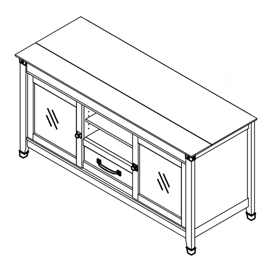
Entertainment Credenza
Carson Forge Collection | 412922
Need help? Visit Sauder.com to view video assembly tips or chat with a live rep.
Prefer the phone? Call 1-800-523-3987.
Share your journey!
It stands. You sit.
A thing of beauty,
this one.
NOTE: THIS INSTRUCTION
BOOKLET CONTAINS IMPORTANT
SAFETY INFORMATION.
PLEASE READ AND KEEP FOR
FUTURE REFERENCE.
English pg 1-28
Français pg 29-32
Español pg 33-36
Lot # 372783
05/18/15
Purchased: __________________
Be sure to give us a ring before
making any returns. 1-800-523-3987
Advertisement

Related Manuals for Sauder Entertainment Credenza 412922


Summary of Contents for Sauder Entertainment Credenza 412922
- Page 1 Carson Forge Collection | 412922 NOTE: THIS INSTRUCTION BOOKLET CONTAINS IMPORTANT SAFETY INFORMATION. Need help? Visit Sauder.com to view video assembly tips or chat with a live rep. PLEASE READ AND KEEP FOR FUTURE REFERENCE. Prefer the phone? Call 1-800-523-3987.
- Page 2 • Check the size and weight of your TV. Compare it to the diagram below – before you begin assembly! • This Sauder unit is designed for use with televisions weighing less than 135 pounds. Never use with a TV that weighs more.
-
Page 3: Part Identifi Cation
FLIP TOP (1) LEFT FRONT LEG (1) LEFT DRAWER SIDE (1) BOTTOM (1) RIGHT FRONT LEG (1) DRAWER BACK (1) SMALL BOTTOM (1) REAR LEG (2) D701 DRAWER BOTTOM (1) SHELF (1) DRAWER FRONT (1) D701 www.sauder.com/services 412922 Page 3... - Page 4 Surface will be damaged. XX BACKPLATE - 2 KNOB - 2 CORD CLIP - 4 02/ 02 2 6 9 2 3 2 269232 (Refer to the last step for proper location and application) Page 4 412922 www.sauder.com/services...
- Page 5 GGG BLACK 9/16" LARGE HEAD SCREW - 18 HHH SILVER 1/2" MACHINE SCREW - 2 BLACK 1/2" FLAT HEAD SCREW - 14 NAIL - 60 30S BLACK 1-9/16" FLAT HEAD SCREW - 4 GOLD 5/16" FLAT HEAD SCREW - 8 www.sauder.com/services 412922 Page 5...
- Page 6 Look for this icon. It means a Step 1 video assembly tip is available at www.sauder.com/services/tips Assemble your unit on a carpeted fl oor or on the empty å carton to avoid scratching your unit or the fl oor. Scan this QR code or go to this address: http://qr.sauder.com/?ID=1128...
- Page 7 Turn six CAM SCREWS (8F) into the FRONT LEGS (O and P). å Fasten a CORNER ACCENT (NN) to each FRONT LEG (O and P). å Use two SILVER 5/8" MACHINE SCREWS (EEE). SILVER 5/8" MACHINE SCREW (2 used in this step) www.sauder.com/services 412922 Page 7...
- Page 8 Fasten the FRONT LEGS (O and P) to the ENDS (A and B). å Tighten six HIDDEN CAMS. Remember: Righty tighty. Lefty loosey. r f a w i t r f a w i t Angled edge Angled edge Page 8 412922 www.sauder.com/services...
- Page 9 Apply pressure with your hands as you guide the MOLDINGS over the SCREWS and onto the END. BLACK 9/16" FLAT HEAD SCREW Shoulder (8 used in this step) BLACK 2-1/4" FLAT HEAD SCREW (6 used in this step) Angled edge www.sauder.com/services 412922 Page 9...
- Page 10 UPRIGHTS (C and D). Use four GOLD 5/16" FLAT HEAD SCREWS (3S) through holes #1 and #4. GOLD 5/16" FLAT HEAD SCREW (4 used in this step) Roller end Curved edge Curved edge Roller end Page 10 412922 www.sauder.com/services...
- Page 11 Tighten Risk of damage or Arrow injury. HIDDEN CAMS must be completely Arrow Maximum tightened. HIDDEN 210 degrees CAMS that are not completely tightened may loosen, and parts may separate. To Minimum completely tighten: 190 degrees www.sauder.com/services 412922 Page 11...
- Page 12 Fasten the ENDS (A and B) to the BOTTOM (G). Tighten å four HIDDEN CAMS. These holes must be here. r f a w i t BLACK 1-7/8" FLAT HEAD SCREW (4 used in this step) Maximum Arrow 210 degrees Minimum 190 degrees Page 12 412922 www.sauder.com/services...
- Page 13 BLACK 1-7/8" FLAT HEAD SCREW (3 used in this step) i t h o f a c S u r D E N H I D r f a w i t Maximum Arrow 210 degrees Minimum 190 degrees www.sauder.com/services 412922 Page 13...
- Page 14 Push four CORD CLIPS (YY) into the holes in the TOP (E). å Fasten the TOP (E) to the ENDS (A and B) UPRIGHTS (C and D), å and SMALL BACK (J). Tighten nine HIDDEN CAMS. Maximum Arrow 210 degrees Minimum 190 degrees Page 14 412922 www.sauder.com/services...
- Page 15 SKIRT. Now, fasten the SKIRT to the ENDS (A and B) and å BOTTOM (G). Use fi ve BLACK 9/16" LARGE HEAD SCREWS (GGG). BLACK 9/16" LARGE HEAD SCREW (10 used in this step) www.sauder.com/services 412922 Page 15...
- Page 16 Step 11 Turn your unit onto its top. å Don't worry. It isn't Push a FOOT (JJ) over the bottom edge of each LEG (O, P, and Q). å Rome. This can be built in a day. Page 16 412922 www.sauder.com/services...
- Page 17 Final adjustments will be made after the unit is standing upright. These holes must be here. These holes must line up over the UPRIGHTS (C and D). BROWN 1-5/8” FLAT HEAD SCREW (4 used in this step) Turn completely in. www.sauder.com/services 412922 Page 17...
- Page 18 Use six BLACK 1/2" FLAT HEAD SCREWS (JJJ). Push four BUMPERS (OO) into the FLIP TOP (F). å SW is stamped into this HINGE for identifi cation. BLACK 1/2" FLAT HEAD SCREW (6 used in this step) Page 18 412922 www.sauder.com/services...
- Page 19 The FLIP-TOP will sit slightly higher (horizontal adjustment screws) than the TOP. Floor Turn the ADJUSTABLE FOOT downward until it touches the fl oor. IMPORTANT: The ADJUSTABLE FOOT should not extend beyond the bottom edges of the LEGS. www.sauder.com/services 412922 Page 19...
- Page 20 å MOLDING (X). the ENDS (A and B). Use two BLACK 9/16" LARGE HEAD SCREWS (GGG). BLACK 9/16" LARGE HEAD SCREW (4 used for the METAL BRACKETS) Rounded edge Maximum Arrow 210 degrees Minimum 190 degrees Page 20 412922 www.sauder.com/services...
- Page 21 Step 16 Fasten the HINGES (UU) to the DOORS (K). Use eight å BLACK 1/2" FLAT HEAD SCREWS (JJJ). BLACK 1/2" FLAT HEAD SCREW (8 used in this step) www.sauder.com/services 412922 Page 21...
- Page 22 DOOR (K) where they come in contact with the UPRIGHT (D). Hinge Repeat this step for the other DOOR. å (4 used) BLACK 1-1/8" MACHINE SCREW (2 used in this step) Page 22 412922 www.sauder.com/services...
- Page 23 To adjust the DOORS in or out (depth), loosen the mounting screw one turn å and move the DOORS in or out, as needed. Tighten the mounting screw after making adjustments. Mounting screw (depth) Adjusting screw (horizontal) (vertical adjustment) www.sauder.com/services 412922 Page 23...
- Page 24 BACK (D62). Use four BLACK 1-9/16" FLAT HEAD SCREWS (30S). Slide the DRAWER BOTTOM (D701) into the grooves in the å DRAWER SIDES (D44 and D45) and DRAWER BACK (D62). BLACK 1-9/16" FLAT HEAD SCREW (4 used in this step) Groove D701 Page 24 412922 www.sauder.com/services...
- Page 25 BRACKETS. Use four BLACK 9/16" LARGE HEAD SCREWS (GGG). Separate the DRAWER FRONT BRACKETS (II) and slide them into the grooves in the DRAWER SIDES. BLACK 9/16" LARGE HEAD SCREW (4 used in this step) Push down Groove www.sauder.com/services 412922 Page 25...
- Page 26 Fasten a PULL (PP) to the DRAWER FRONT (R). Use two SILVER å 1/2" MACHINE SCREWS (HHH). Roller end SILVER 1/2" MACHINE SCREW (2 used for the PULL) Roller end GOLD 5/16" FLAT HEAD SCREW (4 used for the SLIDES) Page 26 412922 www.sauder.com/services...
- Page 27 To make adjustments to the drawer, loosen the SCREWS in the å DRAWER FRONT BRACKETS, make needed adjustments, and tighten the SCREWS. (20 used) Place the roller on the SLIDE behind the roller on the RAIL. www.sauder.com/services 412922 Page 27...
- Page 28 - The base of the TV must be able to sit completely on this shelf. 10 lbs. 135 lbs. 20 lbs. 20 lbs. 20 lbs. 20 lbs. 20 lbs. 10 lbs. 20 lbs. 40 lbs. total Page 28 412922 www.sauder.com/services...
-
Page 29: Français
EXTRÉMITÉ DROITE ................1 CONSOLE À ÉQUERRE ..............5 pour future référence. EXTRÉMITÉ GAUCHE ................ 1 CONSOLE EN MÉTAL ...............2 Pour contacter Sauder MONTANT DROIT ................. 1 CONSOLE DE DEVANT DE TIROIR ......... 1 en ce qui concerne cet MONTANT GAUCHE ................1 PIED .........................4... - Page 30 ! celle-ci se trouve contre les PIEDS AVANT (O et P). • Cette unité Sauder est conçue pour les téléviseurs pesant moins de 61,2 Fixer les PIEDS ARRIÈRE (Q) aux EXTRÉMITÉS (A et B). Utiliser six VIS kg.
- Page 31 Fixer les CHARNIÈRES SW (VV) sur le DESSUS RELEVABLE (F). Utiliser Fixer les CHARNIÈRES (UU) aux PORTES (K). Utiliser huit VIS NOIRES six VIS NOIRES TÊTE PLATE 13 mm (JJJ). TÊTE PLATE 13 mm (JJJ). Enfoncer quatre TAMPONS (OO) dans le DESSUS RELEVABLE (F). www.sauder.com/services 412922 Page 31...
- Page 32 Séparer les CONSOLES DE DEVANT DE TIROIR (II) et les enfi ler dans les rainures des CÔTÉS DE TIROIR (D44 et D45). Fixer le DEVANT DE TIROIR (R) aux CONSOLES DE DEVANT DE TIROIR. Utiliser quatre VIS NOIRES TÊTE LARGE 14 mm (GGG). Page 32 412922 www.sauder.com/services...
-
Page 33: Español
EXTREMO IZQUIERDO ..................1 PATA CENTRAL ..................1 pour future référence. PARAL DERECHO ....................1 BASE DE PATA ..................1 Pour contacter Sauder PARAL IZQUIERDO .....................1 TARJETA CON TOPES DE FIELTRO ........1 en ce qui concerne cet ACENTO DE ESQUINA ..............2 PANEL SUPERIOR ....................1... - Page 34 - antes de comenzar el ensamblaje! las PATAS DELANTERAS (O y P). • Esta unidad Sauder está diseñada para ser usada con televisores Fije las PATAS POSTERIORES (Q) a los EXTREMOS (A y B). Utilice seis cuyo peso sea inferior a 61,2 Kg. Nunca la use para un televisor de TORNILLOS NEGROS DE CABEZA PERDIDA de 57 mm (AAA).
- Page 35 TORNILLOS NEGROS DE CABEZA PERDIDA de 13 mm (JJJ). Fije las BISAGRAS (UU) a las PUERTAS (K). Utilice ocho TORNILLOS Presione cuatro TOPES (OO) en el PANEL SUPERIOR ABATIBLE (F). NEGROS DE CABEZA GRANDE de 13 mm (JJJ). www.sauder.com/services 412922 Page 35...
- Page 36 Separe las MÉNSULAS DE CARA DE CAJÓN (II) y deslícelas dentro de las ranuras de los LADOS DE CAJÓN (D44 y D45). Fije la CARA DE CAJÓN (R) a las MÉNSULAS DE CARA DE CAJÓN. Utilice cuatro TORNILLOS NEGROS DE CABEZA GRANDE de 14 mm (GGG). Page 36 412922 www.sauder.com/services...
-
Page 37: Safety
équipé. • Blessure physique. Le mobilier peut être très lourd. • Ne pas pousser le mobilier, surtout sur la moquette. Se faire aider par une autre personne pour soulever l’élément et le mettre en place. www.sauder.com/services 412922 Page 37... - Page 38 • Lesión física. El mobiliario puede ser • No empuje la unidad, especialmente muy pesado. sobre un piso alfombrado. Pide la ayuda de otra persona en levantar la unidad y colocarla en lugar. Page 38 412922 www.sauder.com/services...
-
Page 39: Warranty
GARANTIE LIMITÉE DE 5 ANS 1. Sauder Woodworking Co. (Sauder®) off re une couverture de garantie limitée à l’ a cheteur 4. La présente garantie ne s’ a pplique qu’ a ux défauts garantis qui se produisent pour initial du présent produit pendant une période de cinq ans à... -
Page 40: Page.
Dear Valued Customer: So, how did it go? Thanks so much for choosing Sauder® furniture. I hope the Set a world record for speed? purchase and assembly process was a positive experience Feeling good about yourself? and you feel good about the furniture you just built. If you Nice.
Need help?
Do you have a question about the Entertainment Credenza 412922 and is the answer not in the manual?
Questions and answers