Table of Contents
Advertisement
Quick Links
sauder.com
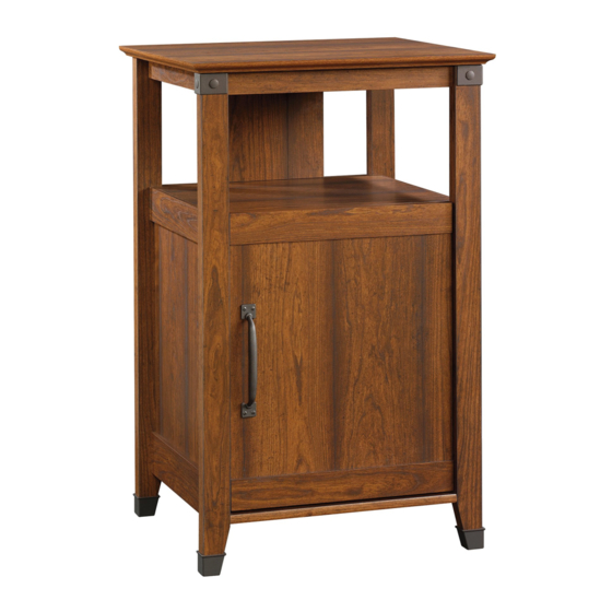
Technology Pier
Carson Forge Collection | 412923
Need help? Visit Sauder.com to view video assembly tips or chat with a live rep.
Prefer the phone? Call 1-800-523-3987.
Share your journey!
Spruce up. Charge up.
NOTE: THIS INSTRUCTION
BOOKLET CONTAINS IMPORTANT
SAFETY INFORMATION.
PLEASE READ AND KEEP FOR
FUTURE REFERENCE.
English pg 1-19
Français pg 20-22
Español pg 23-25
Lot # 357478
12/11/13
Purchased: __________________
Be sure to give us a ring before
making any returns. 1-800-523-3987
Advertisement
Table of Contents

Subscribe to Our Youtube Channel
Related Manuals for Sauder Carson Forge Technology Pier 412923


Summary of Contents for Sauder Carson Forge Technology Pier 412923
- Page 1 Carson Forge Collection | 412923 NOTE: THIS INSTRUCTION BOOKLET CONTAINS IMPORTANT SAFETY INFORMATION. Need help? Visit Sauder.com to view video assembly tips or chat with a live rep. PLEASE READ AND KEEP FOR FUTURE REFERENCE. Prefer the phone? Call 1-800-523-3987.
- Page 2 Table of Contents Assembly Tools Required Part Identifi cation No. 2 Phillips Screwdriver Tip Shown Actual Size Hardware Identifi cation Assembly Steps 5-19 Hammer Not actual size Français 20-22 Español 23-25 Safety Warranty Page 2 412923 www.sauder.com/services...
-
Page 3: Part Identification
DOOR (1) UPPER END MOLDING (2) TOP (1) ADJUSTABLE SHELF (1) LOWER END MOLDING (2) BOTTOM (1) RIGHT FRONT LEG (1) TOP SIDE MOLDING (2) SHELF (1) LEFT FRONT LEG (1) SMALL BACK (1) REAR LEG (2) www.sauder.com/services 412923 Page 3... -
Page 4: Hardware Identification
BLACK 1-7/8" FLAT HEAD SCREW - 3 BLACK 9/16" LARGE HEAD SCREW - 13 BLACK 9/16" FLAT HEAD SCREW - 8 BLACK 1/2" FLAT HEAD SCREW - 4 SILVER 1/2" MACHINE SCREW - 4 NAIL - 22 Page 4 412923 www.sauder.com/services... - Page 5 Assemble your unit on a carpeted fl oor or on the empty å carton to avoid scratching your unit or the fl oor. To begin assembly, push a SAUDER TWIST-LOCK® å FASTENER (Q) into the large holes in the ENDS (A and B) and BOTTOM (D).
- Page 6 Do not tighten the HIDDEN CAMS in this step. Arrow Arrow Arrow Do not insert CAM DOWELS into these parts. Insert the metal end of the CAM DOWEL into the HIDDEN CAM. Arrow (9 used) (5 used) Page 6 412923 www.sauder.com/services...
- Page 7 Step 3 Turn four CAM SCREWS (8F) into the å FRONT LEGS (J and K). www.sauder.com/services 412923 Page 7...
- Page 8 (2 used in this step) r f a I S T w i t - L O Edge with ® TWIST-LOCK® FASTENERS r f a I S T w i t - L O ® Angled edge Angled edge Page 8 412923 www.sauder.com/services...
- Page 9 Step 5 Fasten the BOTTOM (D) to the ENDS (A and B). Tighten å ® How to use the SAUDER TWIST-LOCK FASTENER four TWIST-LOCK® FASTENERS. 1. Insert the dowel end of the FASTENER into the hole of the Fasten the SHELF (E) to the ENDS (A and B). Tighten four å...
- Page 10 Apply pressure with your hands as you guide the MOLDINGS over the SCREWS and onto the ENDS. The LOWER END MOLDINGS (O) are wider than the UPPER END MOLDINGS (N). Shoulder BLACK 9/16" FLAT HEAD SCREW (8 used in this step) Page 10 412923 www.sauder.com/services...
- Page 11 å BLACK 1-7/8" FLAT HEAD SCREWS (GG). BLACK 2-1/4" FLAT HEAD SCREW (4 used in this step) Small holes must face up. Angled edge Angled edge BLACK 1-7/8" FLAT HEAD SCREW (2 used in this step) www.sauder.com/services 412923 Page 11...
- Page 12 Carefully cut out the holes needed. Turn two CORD CLIPS (X) into the SMALL BACK (F). å NOTE: The CORD CLIPS are used to hold your cord against the BACK. å NAIL (22 used in this step) Page 12 412923 www.sauder.com/services...
- Page 13 Tighten Risk of damage or Arrow injury. HIDDEN CAMS must be completely Arrow Maximum tightened. HIDDEN 210 degrees CAMS that are not completely tightened may loosen, and parts may separate. To Minimum completely tighten: 190 degrees www.sauder.com/services 412923 Page 13...
- Page 14 NOTE: There are no pre-drilled holes in the MOLDINGS. å The SCREWS will tighten into the groove. Using your hammer, gently tap a FOOT (Z) å onto each LEG (J, K, and L). BLACK 9/16" LARGE HEAD SCREW (12 used in this step) Page 14 412923 www.sauder.com/services...
-
Page 15: Option Page
NOTE: The following steps show the DOOR on the right. å - DOOR ON LEFT - - OPTION PAGE - Do not fasten the door in this step. - DOOR ON RIGHT - www.sauder.com/services 412923 Page 15... - Page 16 Step 12 Fasten two HINGES (U) to the DOOR (H). Use four BLACK å 1/2" FLAT HEAD SCREWS (JJ). BLACK 1/2” FLAT HEAD SCREW (4 used in this step) Page 16 412923 www.sauder.com/services...
- Page 17 HINGE part way out of the slot. Retighten the mounting screw before fastening the HINGE to the END. Fasten a PULL (CC) to the DOOR (H). Use two SILVER 1/2" å MACHINE SCREWS (KK). Mounting screw SILVER 1/2" MACHINE SCREW (2 used in this step) www.sauder.com/services 412923 Page 17...
-
Page 18: Door Adjustments
To adjust the DOOR in or out (depth), loosen the mounting screw one turn and move the DOOR in or out, as needed. å Tighten the mounting screw after making adjustments. Mounting screw (depth) Adjusting screw (horizontal) (vertical adjustment) Page 18 412923 www.sauder.com/services... - Page 19 (1 used into a stud in your wall) To cover HIDDEN CAMS BLACK 9/16" LARGE HEAD SCREW (1 used into the top of your unit) (6 used) 40 lbs. 30 lbs. 25 lbs. 40 lbs. (4 used) www.sauder.com/services 412923 Page 19...
-
Page 20: Liste De Pièces
QUANTITÉ d’ a chat de cet élément et conserver le livret pour future référence. EXTRÉMITÉ DROITE ..........1 FIXATION TWIST-LOCK® ........8 Pour contacter Sauder EXTRÉMITÉ GAUCHE ..........1 EXCENTRIQUE ESCAMOTABLE .....9 en ce qui concerne cet DESSUS ................1 VIS D'EXCENTRIQUE ..........4 élément, faire référence au numéro de lot et... - Page 21 Aligner la rainure des MOULURES sur les têtes des VIS dans les Pour commencer l'assemblage, enfoncer une FIXATION TWIST- EXTRÉMITÉS. Enfi ler les MOULURES D'EXTRÉMITÉ (N et O) sur LOCK® SAUDER (Q) dans les gros trous des EXTRÉMITÉS (A et B) les EXTRÉMITÉS (A et B). et le DESSOUS (D).
- Page 22 fi xation pour glisser le CHARNIÈRE partiellement hors de la fente. Resserrer la vis de fi xation avant de monter la CHARNIÈRE à l’EXTRÉMITÉ. Fixer une POIGNÉE (CC) à la PORTE (H). Utiliser deux VIS ARGENTÉES À MÉTAUX 13 mm (KK). Page 22 412923 www.sauder.com/services...
-
Page 23: Lista De Partes
SUJETADOR TWIST-LOCK® ........8 et conserver le livret pour future référence. EXCÉNTRICO ESCONDIDO .......9 EXTREMO IZQUIERDO ............1 Pour contacter Sauder BIELA DE EXCÉNTRICO ........4 PANEL SUPERIOR ..............1 en ce qui concerne cet PASADOR DE EXCÉNTRICO ......5 FONDO .................... 1 élément, faire référence... - Page 24 Para comenzar el ensamblaje, empuje un SUJETADOR TWIST- TORNILLOS de los EXTREMOS. Deslice las MOLDURAS DE LOCK® SAUDER (Q) dentro de los agujeros grandes de los EXTREMO (N y O) sobre los EXTREMOS (A y B). EXTREMOS (A y B) y del FONDO (D).
- Page 25 BISAGRA parcialmente fuera de la ranura. Vuelva a apretar el tornillo de montaje antes de montar la BISAGRA al EXTREMO. Fije un TIRADOR (CC) a la PUERTA (H). Utilice dos TORNILLOS PLATEADOS PARA METAL de 13 mm (KK). www.sauder.com/services 412923 Page 25...
- Page 26 Además, el peso y la ubicación del tubo de imagen tienden a causar la inestabilidad de televisores y son propensos a inclinarse hacia adelante. Page 26 412923 www.sauder.com/services...
-
Page 27: Year Limited Warranty
à compter de la date d'achat la première fois et qui sont signalés à Sauder dans les limites de couverture de la contre tout défaut de matériaux ou de fabrication des composantes de mobilier Sauder. - Page 28 Dear Valued Customer: So, how did it go? Thanks so much for choosing Sauder® furniture. I hope the Set a world record for speed? purchase and assembly process was a positive experience Feeling good about yourself? and you feel good about the furniture you just built. If you Nice.
Need help?
Do you have a question about the Carson Forge Technology Pier 412923 and is the answer not in the manual?
Questions and answers