
Subscribe to Our Youtube Channel
Related Manuals for CyberPower MBP60AHVIEC82U


Summary of Contents for CyberPower MBP60AHVIEC82U
- Page 1 Userˊs Manual MBP60AHVIEC82U (Manual Bypass PDU) Cyber Power Systems, Inc. www.cyberpower.com K01-C000256-01...
-
Page 2: Table Of Contents
CONTENT: 1. SAFETY ..................1 2. MANUAL BYPASS PDU CONTAINS: ..........2 3. BASIC OPERATION ................ 3 3.1. Manual Bypass Schematic ..............3 3.2. Front/Rear Panel Description .............3 3.3. Electrical Specifications ...............4 3.4. Operating Environment ...............4 3.5. Dimensions and Weights ..............4 3.6. -
Page 3: Safety
SAVE THESE INSTRUCTIONS. This manual contains important instructions that should be followed during installation and maintenance of the Manual Bypass Module and UPS. 1. SAFETY The system has its own power source when connected to the UPS (UPS battery). Consequently, the power outlets may be energized even if the system is disconnected from the AC power source. -
Page 4: Manual Bypass Pdu Contains
2. MANUAL BYPASS PDU CONTAINS: User’s Manual Manual Bypass PDU UPS Input Cable(BLUE) Terminal Flat Head Screws: UPS Output Cable(GRAY) M4X8L*8PCS Round Head Screws: Rackmount Ears*2PCS M3X6L*4PC... -
Page 5: Basic Operation
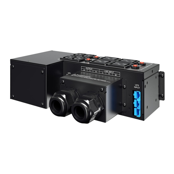
3. BASIC OPERATION 3.1. Schematic OUTPUT LINE MANUAL UPS Input UPS Output INPUT BYPASS Connector Connector SWITCH 3.2. Top/Rear Panel Description ① Manual Bypass Switch The Manual Bypass Module has a manual Bypass rotary switch with two... -
Page 6: Electrical Specifications
positions: UPS → the load is supplied by the UPS. BYPASS → the load is supplied directly by the AC power source. ② UPS Output Connector Use the connector to attach the Manual Bypass Module to the UPS Output. ③... -
Page 7: Hardware Installation
3.6. Hardware Installation 3.6.1. Rear Installation: 3.6.2. Rack Installation:... -
Page 8: Electrical Installation
4. ELECTRICAL INSTALLATION This type of connection must be carried out by qualified electrical personnel. Refer to the UPS User Manual for circuit breaker current rating and the cable cross-sections, the circuit breaker has to be installed upstream the Manual Bypass Module Normal AC source ... -
Page 9: Ups Maintenance With Manual Bypass Module
connector. Reinstall all Useful safety protection covers Connect the battery cable (refer to the UPS User Manual). Set the Manual Bypass Module upstream Breaker to the "ON" position. Set the UPS Input Breaker to the "ON" position and verify the UPS is in Bypass mode. -
Page 10: How To Return The Ups With Manual Bypass Module
Hazardous voltage and lost load risk: do not manipulate the Manual Bypass Switch without UPS connected the Input and Output cables. Cyber Power Systems, Inc. www.cyberpower.com 6F, No. 32, Sec. 1, Chenggong Rd., Nangang District, Taipei 115, Taiwan © Entire contents copyright 2013 Cyber Power Systems, Inc., All rights reserved.
Need help?
Do you have a question about the MBP60AHVIEC82U and is the answer not in the manual?
Questions and answers