
Related Manuals for Mitsubishi Electric MELSEC iQ-R R60TD8-G


Summary of Contents for Mitsubishi Electric MELSEC iQ-R R60TD8-G
- Page 1 MELSEC iQ-R Channel Isolated Thermocouple Input Module/Channel Isolated RTD Input Module User's Manual (Startup) -R60TD8-G -R60RD8-G...
-
Page 3: Safety Precautions
SAFETY PRECAUTIONS (Read these precautions before using this product.) Before using this product, please read this manual and the relevant manuals carefully and pay full attention to safety to handle the product correctly. The precautions given in this manual are concerned with this product only. For the safety precautions of the programmable controller system, refer to the MELSEC iQ-R Module Configuration Manual. - Page 4 [Design Precautions] WARNING ● Configure safety circuits external to the programmable controller to ensure that the entire system operates safely even when a fault occurs in the external power supply or the programmable controller. Failure to do so may result in an accident due to an incorrect output or malfunction. (1) Emergency stop circuits, protection circuits, and protective interlock circuits for conflicting operations (such as forward/reverse rotations or upper/lower limit positioning) must be configured external to the programmable controller.
- Page 5 [Design Precautions] WARNING ● When connecting an external device with a CPU module or intelligent function module to modify data of a running programmable controller, configure an interlock circuit in the program to ensure that the entire system will always operate safely. For other forms of control (such as program modification, parameter change, forced output, or operating status change) of a running programmable controller, read the relevant manuals carefully and ensure that the operation is safe before proceeding.
- Page 6 [Design Precautions] CAUTION ● Do not install the control lines or communication cables together with the main circuit lines or power cables. Keep a distance of 100mm or more between them. Failure to do so may result in malfunction due to noise. ●...
- Page 7 [Installation Precautions] CAUTION ● Use the programmable controller in an environment that meets the general specifications in the Safety Guidelines included with the base unit. Failure to do so may result in electric shock, fire, malfunction, or damage to or deterioration of the product. ●...
- Page 8 [Wiring Precautions] CAUTION ● Individually ground the FG and LG terminals of the programmable controller with a ground resistance of 100 ohms or less. Failure to do so may result in electric shock or malfunction. ● Use applicable solderless terminals and tighten them within the specified torque range. If any spade solderless terminal is used, it may be disconnected when the terminal screw comes loose, resulting in failure.
- Page 9 [Startup and Maintenance Precautions] WARNING ● Do not touch any terminal while power is on. Doing so will cause electric shock or malfunction. ● Correctly connect the battery connector. Do not charge, disassemble, heat, short-circuit, solder, or throw the battery into the fire. Also, do not expose it to liquid or strong shock. Doing so will cause the battery to produce heat, explode, ignite, or leak, resulting in injury and fire.
- Page 10 [Startup and Maintenance Precautions] CAUTION ● When connecting an external device with a CPU module or intelligent function module to modify data of a running programmable controller, configure an interlock circuit in the program to ensure that the entire system will always operate safely. For other forms of control (such as program modification, parameter change, forced output, or operating status change) of a running programmable controller, read the relevant manuals carefully and ensure that the operation is safe before proceeding.
- Page 11 [Operating Precautions] CAUTION ● When changing data and operating status, and modifying program of the running programmable controller from an external device such as a personal computer connected to an intelligent function module, read relevant manuals carefully and ensure the safety before operation. Incorrect change or modification may cause system malfunction, damage to the machines, or accidents.
-
Page 12: Conditions Of Use For The Product
CONDITIONS OF USE FOR THE PRODUCT (1) Mitsubishi programmable controller ("the PRODUCT") shall be used in conditions; i) where any problem, fault or failure occurring in the PRODUCT, if any, shall not lead to any major or serious accident; ii) where the backup and fail-safe function are systematically or automatically provided outside of the PRODUCT for the case of any problem, fault or failure occurring in the PRODUCT. -
Page 13: Compliance With Emc And Low Voltage Directives
COMPLIANCE WITH EMC AND LOW VOLTAGE DIRECTIVES Method of ensuring compliance To ensure that Mitsubishi programmable controllers maintain EMC and Low Voltage Directives when incorporated into other machinery or equipment, certain measures may be necessary. Please refer to one of the following manuals. •... - Page 14 MEMO...
-
Page 15: Table Of Contents
CONTENTS SAFETY PRECAUTIONS ..............1 CONDITIONS OF USE FOR THE PRODUCT . -
Page 16: Relevant Manuals
RELEVANT MANUALS Manual name [manual number] Description Available form MELSEC iQ-R Channel Isolated Thermocouple Input System configuration, specifications, procedures before operation, wiring, and Print book Module/Channel Isolated RTD Input Module User's operation examples of the channel isolated thermocouple input module and the e-Manual Manual (Startup) channel isolated RTD input module... -
Page 17: Chapter 1 Part Names
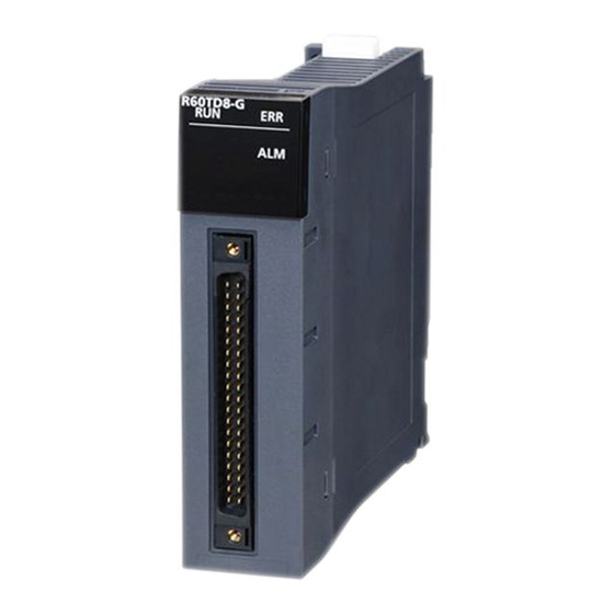
PART NAMES This chapter describes the part names of temperature input modules. Name Description RUN LED Indicates the operating status of the module. On: Normal operation Flashing (1s cycle): In offset/gain setting mode Flashing (400ms cycle): The module for online module change selected Off: 5V power supply interrupted or watchdog timer error occurred, module change for online module change possible ERR LED... - Page 18 MEMO 1 PART NAMES...
-
Page 19: Chapter 2 Specifications
SPECIFICATIONS This chapter describes the performance specifications. Performance Specifications This section describes the performance specifications of temperature input modules. Thermocouple input module Item Specifications Model R60TD8-G Number of analog input channels 8 channels + Cold junction compensation channel per module Output Measured temperature value 16-bit signed binary value (-2700 to 18200) - Page 20 RTD input module Item Specifications Model R60RD8-G Number of analog input channels 8 channels Output Measured temperature value 16-bit signed binary value (-2000 to 8500) Scaling value 16-bit signed binary value Usable resistance temperature detector Pt100 (JIS C 1604-2013, IEC 751:1983) JPt100 (JIS C 1604-1981) Ni100 (DIN 43760 1987) Pt50 (JIS C 1604-1981)
-
Page 21: Chapter 3 Function List
FUNCTION LIST This chapter lists the functions of temperature input modules. For details on the functions, refer to the following. MELSEC iQ-R Channel Isolated Thermocouple Input Module/Channel Isolated RTD Input Module User's Manual (Application) Item Description Input range setting function Allows to select the thermocouple type or resistance temperature detector type to be used as well as the input range for each channel. - Page 22 Item Description Online module change Allows to replace a module without stopping the system. For procedures for the online module change, refer to the following. MELSEC iQ-R Online Module Change Manual Q compatible mode function Allows to convert the layout of buffer memory addresses of a temperature input module to the one equivalent to a MELSEC-Q series module.
-
Page 23: Chapter 4 Procedures Before Operation
PROCEDURES BEFORE OPERATION This chapter describes the procedures before operation. Mounting a module Mount a temperature input module in any desired configuration. Wiring Perform wiring of thermocouples or resistance temperature detectors to a temperature input module. Adding a module Add a temperature input module to a module configuration by using the engineering tool. For details, refer to the following. ... - Page 24 MEMO 4 PROCEDURES BEFORE OPERATION...
-
Page 25: Chapter 5 Wiring
WIRING This chapter describes the wiring of a temperature input module. Wiring Precautions Check the signal layout and then correctly wire a temperature input module. For the signal layout, refer to the following. Page 24 Signal layout of connectors for external devices Connector for external devices Precautions •... -
Page 26: External Wiring
External Wiring Signal layout of connectors for external devices The following tables show the signal layout of external device connectors of a temperature input module. Thermocouple input module Pin layout (viewed from the CH1 to CH8, RTD front of the module) Pin number Signal name Pin number... - Page 27 RTD input module Pin layout (viewed from the CH1 to CH8 front of the module) Pin number Signal name Pin number Signal name CH1 A1 CH1 B1 CH1 b1 CH2 b2 CH2 A2 CH2 B2 CH3 A3 CH3 B3 ...
-
Page 28: External Wiring Examples
External wiring examples This section shows the examples of external wiring. Thermocouple input module Follow the procedure below for wiring. Install a relay terminal block. Connect thermocouples and compensation lead wires to the relay terminal block. When With cold junction compensation (0) is set to 'Cold junction compensation with/without setting' (Un\G298), connect the provided cold junction compensation resistor (RTD) to the relay terminal block. - Page 29 If the cold junction compensation resistor (RTD) and the reference junction of the thermocouple (or the reference junction of the compensation lead wire) are not connected to the same place (relay terminal block), the (ambient) temperature difference may lead to a faulty measured temperature value. In addition, if an incorrect wire is connected between A and B or B and C (case 1 or case 2 below), the (ambient) temperature difference may lead to a faulty measured temperature value.
- Page 30 RTD input module Follow the procedure below for wiring. Install a relay terminal block. Connect resistance temperature detectors to the relay terminal block. Wire the relay terminal block to a RTD input module using an external device connector. RTD input module Relay terminal block External device...
-
Page 31: To Use A Connector/Terminal Block Converter Module
*3 The RTD- and RTDG are connected in the connector/terminal block converter module. Therefore the connection of RTD- and RTDG at the terminal block is not required. Product name Model Remarks Contact Connector/terminal block converter module FA-LTB40TDG Your local Mitsubishi Electric sales office or representative Dedicated cable FA-CBL05Q68TDG Cable length: 0.5m FA-CBL10Q68TDG Cable length: 1.0m FA-CBL20Q68TDG Cable length: 2.0m FA-CBL30Q68TDG Cable length: 3.0m... - Page 32 Shield Shield *1 Ground the shields. Product name Model Remarks Contact Connector/terminal block converter module FA-LTB40RD3G Your local Mitsubishi Electric sales office or representative Dedicated cable FA-CBL05Q68RD3G Cable length: 0.5m FA-CBL10Q68RD3G Cable length: 1.0m FA-CBL20Q68RD3G Cable length: 2.0m FA-CBL30Q68RD3G Cable length: 3.0m...
-
Page 33: Chapter 6 Operation Examples
OPERATION EXAMPLES This chapter describes the programming procedure and the basic program of a temperature input module. Programming Procedure Take the following steps to create a program for running a temperature input module: Set parameters. Page 32 Parameter settings Create a program. Page 35 Program examples Program Examples System configuration... - Page 34 Parameter settings Perform an initial setting in the module parameter of the engineering tool. The refresh settings do not need to be changed here. For details on the module parameter, refer to the following. MELSEC iQ-R Channel Isolated Thermocouple Input Module/Channel Isolated RTD Input Module User's Manual (Application) ■Basic setting Configure the basic setting as shown below.
- Page 35 ■Application setting Configure the application setting as shown below. 6 OPERATION EXAMPLES 6.2 Program Examples...
- Page 36 Label settings GX Works3 provides functions that support the creation of a program. The following table lists the module labels and global labels used for the program examples in this section. There is no need to change the settings of the module labels. For details on the global labels, refer to the following. ...
- Page 37 Program examples ■Program example 1 • This program is an example to read and save the measured temperature values of CH1, CH3, and CH7, and the scaling value of CH5. (0) CH1 Measured temperature value, CH3 Measured temperature value, CH5 Scaling value, and CH7 Measured temperature value are to be read. ■Program example 2 •...
- Page 38 ■Program example 4 • This program is an example to perform the processing at the time of disconnection detection in CH7. (0) At the time when disconnection is detected in CH7, the processing is to be performed. ■Program example 5 •...
-
Page 39: Chapter 7 Offset/Gain Setting
OFFSET/GAIN SETTING Using the user range setting requires setting the offset and gain values. Access to the offset/gain setting window in the engineering tool to set the offset and gain values. Setting Procedure The setting procedure for the offset/gain setting of a temperature input module is as follows: [Tool] ... - Page 40 Check the channel where the offset/gain setting is performed. Write the temperature setting value corresponding to the offset value to "Offset Temperature Setting Value". Click [Offset Setting] button. Apply a value that becomes an offset value to the terminal of the corresponding channel, and click [Yes] button.
- Page 41 Click [Yes] button. 7 OFFSET/GAIN SETTING 7.1 Setting Procedure...
-
Page 42: Appendices
APPENDICES Appendix 1 Accuracy This section describes the accuracy of a temperature input module. Accuracy of the thermocouple input module The accuracy () is calculated from the following formula. C : Conversion accuracy : Temperature characteristics : Operating ambient temperature change : Cold junction compensation accuracy Note that the operating ambient temperature change indicates the extent to which the operating ambient temperature is out of the range of 255. - Page 43 Usable Temperature Conversion accuracy Temperature characteristics Maximum Effect per wiring thermocouple measuring (for operating ambient (for 1 of operating ambient temperature resistance 1 range temperature 255) temperature change) error at ambient temperature 55 -210 to -40 0.2...
- Page 44 Accuracy of the RTD input module The accuracy () is calculated from the following formula. + AL : Conversion accuracy : Allowance of the resistance temperature detector used • Allowance of Pt100 (JIS C 1604-1997, IEC 751:1983) Class Allowance (0.15 + 0.002|t|) (0.3 + 0.005|t|)...
-
Page 45: Appendix 2 External Dimensions
Appendix 2 External Dimensions The following figure shows the external dimensions of a temperature input module. 27.8 (Unit: mm) APPENDICES Appendix 2 External Dimensions... -
Page 46: Index
INDEX 0 to 9 ....23 40-pin connector crimping tool ..... . . 23 40-pin connectors . - Page 47 MEMO...
-
Page 48: Revisions
Japanese manual number: SH-081492-C This manual confers no industrial property rights or any rights of any other kind, nor does it confer any patent licenses. Mitsubishi Electric Corporation cannot be held responsible for any problems involving industrial property rights which may occur as a result of using the contents noted in this manual. -
Page 49: Warranty
WARRANTY Please confirm the following product warranty details before using this product. 1. Gratis Warranty Term and Gratis Warranty Range If any faults or defects (hereinafter "Failure") found to be the responsibility of Mitsubishi occurs during use of the product within the gratis warranty term, the product shall be repaired at no cost via the sales representative or Mitsubishi Service Company. -
Page 50: Trademarks
TRADEMARKS The company names, system names and product names mentioned in this manual are either registered trademarks or trademarks of their respective companies. In some cases, trademark symbols such as ' ' or ' ' are not specified in this manual. SH(NA)-081493ENG-C... - Page 52 SH(NA)-081493ENG-C(2008)MEE MODEL: R60TDG-R60RDG-U-IN-E MODEL CODE: 13JX33 HEAD OFFICE : TOKYO BUILDING, 2-7-3 MARUNOUCHI, CHIYODA-KU, TOKYO 100-8310, JAPAN NAGOYA WORKS : 1-14 , YADA-MINAMI 5-CHOME , HIGASHI-KU, NAGOYA , JAPAN When exported from Japan, this manual does not require application to the Ministry of Economy, Trade and Industry for service transaction permission.
Need help?
Do you have a question about the MELSEC iQ-R R60TD8-G and is the answer not in the manual?
Questions and answers