Table of Contents
Advertisement
USER MANUAL
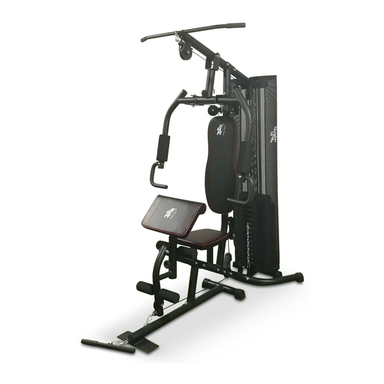
SUPERGAIN TF-7080A
Please Keep For Future Reference
HJ-R2P7-PGFJ
IMPORTANT - Please Read Instructions Fully Before Assembly Or Use
These instructions contain important information which will help you get the best
from your equipment and ensure safe and correct assembly, use and maintenance.
If you need help or have damaged or missing parts,
call the Customer Helpline: 0330 124 0718 (Opening hours: Mon-Fri 9:00am-3:00pm)
or Email: customerservices@fit4home.co.uk
1
Advertisement
Table of Contents

Related Manuals for Fit4Home TF-7080A


Summary of Contents for Fit4Home TF-7080A
- Page 1 USER MANUAL SUPERGAIN TF-7080A Please Keep For Future Reference HJ-R2P7-PGFJ IMPORTANT - Please Read Instructions Fully Before Assembly Or Use These instructions contain important information which will help you get the best from your equipment and ensure safe and correct assembly, use and maintenance.
-
Page 2: Table Of Contents
CONTENTS Safety Information 03, 04 Strength Programme Exercise Guidelines Parts Chart 07,08 Parts List Assembly Instructions Step 1 Step 2 Step 3 Step 4 Step 5 Step 6 Step 7 16-17 Step 8 Step 9 Step 10 Step 11 Exercises Maintenance Declaration... -
Page 3: Safety Information
8. If you need help or have damaged or missing parts, call the Customer Helpline: 03301240718 Telephone Line Opening Hours: Mon – Fri: 9:00 am – 3:00 pm Fit4home Ltd Unit A, Perseverance Business park, Olive Lane Darwen, BB3 3DQ... - Page 4 IMPORTANT SAFETY INFORMATION This exercise equipment is built for optimum safety. However, certain precautions apply whenever you operate a piece of exercise equipment. Be sure to read the entire manual before you assemble or operate your equipment. In particular, note the following safety precautions: Keep children and pets away from the equipment at all times.
-
Page 5: Strength Programme
STRENGTH BUILDING PROGRAMME BEGINNING A STRENGTH BUILDING PROGRAMME Warming Up To begin strength training, it is important to stretch and perform light exercise for 5 to 10 minutes. This helps prepare the body for more strenuous exercise by increasing circulation, raising your body temperature and developing more oxygen to your muscles. -
Page 6: Exercise Guidelines
EXERCISE GUIDELINES Building Muscle and Gaining Weight Unlike aerobic exercise, which emphasizes endurance training, anaerobic exercise focuses on strength training. A gradual weight gain can occur while building the size and strength of muscles. While developing muscle mass, your body adapts to the stress placed upon it. You can modify your diet to include foods such as meat, fish and vegetables. -
Page 7: Parts Chart
PARTS CHART NEEDS DIAGRAM IMAGE... - Page 8 PARTS CHART...
-
Page 9: Parts List
PARTS LIST Description Description Anterior basal canal Vertical support pipe Posterior basal canal SEAT TUBE Guide rod Weight Selection Tube Main support tube Top support pipe Elbow cushion support tube Kicking pipe Butterfly arm bracket Right butterfly arm Left butterfly arm Handle Upper transverse tie rod Low horizontal tie rod... -
Page 10: Assembly Instructions
ASSEMBLY INSTRUCTIONS STEP 1 1. Connect the seat cushion tube (A4) to the rear bottom tube (A3), and use the carriage bolt (B5) washer (B13) and nut (B17). 2. Connect the vertical support tube (A2) to the seat cushion tube (A4) using bolt (B4) washer (B12) and nut (B17). - Page 11 ASSEMBLY INSTRUCTIONS STEP 2 1. Connect the bracket bottom pipe (A3) using washer (B14). 2. Insert the guide rod (A5) through the rubber ring (D2) into the two holes of the rear bottom pipe (A3) and then fix it with bolts (B9) and washer (B15) from the bottom. 3.
-
Page 12: Step 3
ASSEMBLY INSTRUCTIONS STEP 3 1. Connect the main support tube (A7) to the seat cushion pipe (A4) and use bolt (B4) washer (B12) and nut (B17). 2. Install the single pulley bracket (C6) on the main support tube (A7) and fix it with bolt (B6) washer (B12) and nut (B17). -
Page 13: Step 4
ASSEMBLY INSTRUCTIONS STEP 4 1. Place the guide rod (A5) in the top support pipe (A8) and fix it with bolts (B9) and washer (B15). 2. Connect top support pipe (A8) to main support tube (A7) using bolt (B4) washer (B12) and nut (B17). -
Page 14: Step 5
ASSEMBLY INSTRUCTIONS STEP 5 1. Place the metal bushing (C3) in the holes on both sides of the top support tube (A8), then connect the butterfly arm bracket (A11) to the top support tube (A8), and fix it with the double head bolt (B1) washer (B11) and nut (B16). -
Page 15: Step 6
ASSEMBLY INSTRUCTIONS STEP 6 1. Insert the elbow cushion support tube (A9) into the cushion tube (A4) and fix it with the knob bolt (B21). 2. Install sponge iron tube (A18) on seat cushion tube (A4) and insert small sponge (D7) from both sides. -
Page 16: Step 7
ASSEMBLY INSTRUCTIONS STEP 7 1. Connect back cushion bracket (C5) to back cushion (D10), fix it with bolt (B10) and washer (B14),then insert it into the hole on main support tube (A7), and fix it with washer (B13) and nut (B17). - Page 17 ASSEMBLY INSTRUCTIONS...
-
Page 18: Step 8
ASSEMBLY INSTRUCTIONS STEP 8 1. Put the upper wire rope (D13) through the first pulley frame of the top support pipe (A8),put the pulley (D4) and the pulley cover (D5), and fix it with bolts (B8) and nuts (B17). 2. Connect the upper wire rope (D13) through the main support pipe (A7) to the second pulley frame of the top support pipe (A8),place the pulley (D4), and fix it with bolts (D8) and nuts (B17). -
Page 19: Step 9
ASSEMBLY INSTRUCTIONS STEP 9 1. Connect one end of the butterfly arm wire rope (D14) to the hook of the left butterfly arm (A12) and fix it with bolts (B9) and nuts (B18). 2. The butterfly arm wire rope (D14) is wound around the pulley (D3), then the pulley (D3) is connected to the single pulley bracket (C6) on the left side of the main support tube (A7) and fixed with bolts (B8) and nuts (B17). -
Page 20: Step 10
ASSEMBLY INSTRUCTIONS STEP 10 1. Put the bottom wire rope (D15) through the kick pipe (A10), put the short bushing (D16) into the holes on both sides of the kick pipe (A10),then put the pulley (D3), and fix it with bolt (B22) washer (B12) and nut (B17). -
Page 21: Step 11
ASSEMBLY INSTRUCTIONS STEP 11 1. Connect the upper transverse tie rod (A15) to the front end of the upper wire rope (D13) and use a hook (C9) to connect it. 2. Connect the low horizontal tie rod (A16) to the front end of the bottom wire rope (D15) and connect it with the chain (C10) and the hook (C9) at both ends. -
Page 22: Exercises
EXERCISES Warning: Make sure all bolt and nylon nut are tighten enough before using the machine. NEEDS DIAGRAM IMAGE... -
Page 23: Maintenance
MAINTENANCE CARE AND MAINTENANCE 1. Lubricate moving parts with WD-40 or light oil periodically. 2. Inspect and tighten all parts before using the equipment. 3. The equipment can be cleaned using a damp cloth and mild non-abrasive detergent. DO NOT use solvents. 4. -
Page 24: Declaration
We, Importer Fit4home Ltd Unit A, Perseverance Mills, Olive Lane, Darwen BB3 3DQ United Kingdom Declare that the product TF-7080A Home Gym Complies with the essential health and safety requirements of the following directive: Direction for 2014/357/EU for Stationery training equipment...
Need help?
Do you have a question about the TF-7080A and is the answer not in the manual?
Questions and answers