Table of Contents
Advertisement
USER MANUAL
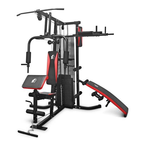
HOME GYM TF-7005A
Please Keep For Future Reference
5T-B0C3-VZLB
IMPORTANT - Please Read Instructions Fully Before Assembly Or Use
These instructions contain important information which will help you get the best
from your equipment and ensure safe and correct assembly, use and maintenance.
If you need help or have damaged or missing parts,
call the Customer Helpline: 0330 124 0718 (Opening hours: Mon-Fri 9:00am-3:00pm)
or Email: customerservices@fit4home.co.uk
1
Advertisement
Table of Contents

Related Manuals for Fit4Home TF-7005A


Summary of Contents for Fit4Home TF-7005A
- Page 1 USER MANUAL HOME GYM TF-7005A Please Keep For Future Reference 5T-B0C3-VZLB IMPORTANT - Please Read Instructions Fully Before Assembly Or Use These instructions contain important information which will help you get the best from your equipment and ensure safe and correct assembly, use and maintenance.
-
Page 2: Table Of Contents
CONTENTS Safety Information 03-04 Parts Chart 05-09 Assembly Instructions 10-26 Step 1 Step 2 Step 3 Step 4 Step 5 Step 6 Step 7 Step 8 17-20 Step 9 21-22 Step 10 Step 11 24-25 Step 12 Declaration... -
Page 3: Safety Information
IMPORTANT SAFETY INFORMATION SAFETY INFORMATION Be sure to read the entire instruction manual before you assemble or use this equipment. Particularly, note the following safety precautions. • Exercising. Do not wear loose clothing that could get caught in the equipment. Appropriate footwear is also required when using the equipment. - Page 4 IMPORTANT SAFETY INFORMATION INSTRUCTIONS WHEN ASSEMBLING • Check you have all the components and tools listed in the instruction manual. • Remove all fittings from the plastic bags and separate them into different groups. • Keep children and animals away from the work area, (small components can causechoking if swallowed).
- Page 5 PARTS LIST...
- Page 6 PARTS LIST...
- Page 7 PARTS LIST...
- Page 8 PARTS LIST...
- Page 9 PARTS LIST...
-
Page 10: Assembly Instructions
ASSEMBLY INSTRUCTIONS STEP 1 1. Use 2 screw bolts (B3), 4 washers (B17) and 2 nuts (B13) to connect the main base frame (A1) to the base frame (A2). 2. Use 2 screw bolts (B3), 4 washers (B17) and 2 nuts (B13) to connect the left and right base frames (A3 and A4) to the base frame (A2). - Page 11 ASSEMBLY INSTRUCTIONS STEP 2 Now position the net plate (D4) over the base frame (A2) as shown in the diagram. Now position 2 rubber bushings (E4) on the net plate (D4), so they are aligned with the base frame (A2) holes. Insert the 2 guide rods (A6) into the base frame (A2), through the rubber bushing...
-
Page 12: Step 3
ASSEMBLY INSTRUCTIONS STEP 3 1. Connect the vertical frame 1 (A7) to the middle of the main base frame (A1). To connect this together you will need to use 4 washers (B17), 2 screw bolts (B3) and 2 nuts (B13). 2. -
Page 13: Step 4
ASSEMBLY INSTRUCTIONS STEP 4 1. Attach the upper frame (A9) to the 2 guide rods (A6). Therefore also being connected to vertical frame 2 (A8). To connect these together you will need to use 2 washers (B18), 5 washers (B17), 2 screw bolts (B9), 2 screw bolts (B3), 4 nuts (B13). 2. -
Page 14: Step 5
ASSEMBLY INSTRUCTIONS STEP 5 Install the seat frame (A11) to vertical frame 1 (A7). Use 2 washers (B17), 2 screw bolts (B3) and 2 nuts (B13) to connect these together. The seat bracket (B25) is installed into the seat frame (A11). To secure use 4 washers (B17) and 2 nuts (B13). -
Page 15: Step 6
ASSEMBLY INSTRUCTIONS STEP 6 1. The vertical support tube (A14) is installed into vertical frame 1 (A7). Use 4 washers (B17), 2 Screw bolts (B4) and 2 nuts (B13). 2. The pulley support (D3) need to be installed near the top of vertical frame 1 (A7). Use 3 washers (B17), 1 screw bolt (B5) and 4 nuts (B13). -
Page 16: Step 7
ASSEMBLY INSTRUCTIONS STEP 7 1. Attach the front press base (A15) to the main upper frame (A10). To secure this you will need to use 1 screw bolt (B1), 2 washers (B16) and 1 nut (B12). 2. Then install the right butterfly and the left butterfly (A16 and A17) onto the front press base (A15). -
Page 17: Step 8
ASSEMBLY INSTRUCTIONS STEP 8 1. The right dip arm and the left dip arm (A19 and A20) need to be connected on both sides of vertical frame 2 (A8). To secure you will need 4 washers (B17), 2 screw bolts (B3) and 2 nuts (B13). - Page 18 ASSEMBLY INSTRUCTIONS...
- Page 19 ASSEMBLY INSTRUCTIONS...
- Page 20 ASSEMBLY INSTRUCTIONS...
-
Page 21: Step 9
ASSEMBLY INSTRUCTIONS STEP 9 1. The selection bar cable (E29) goes through the 1-1pulley (A10). Theninstall pulley (E2) and pulley covers (E1). To secure use 1 screw bolt (B7) and 1 nut (B15). 2. Continuing on the selection bar cable (E29) then goes through the 1-3 pulley block (A7), Install the pulley connecting plates (D2) and pulley... -
Page 22: Step 9
ASSEMBLY INSTRUCTIONS STEP 9 4. Then the selection bar cable (E29) advances through the 1-4 pulley frame (A10), use pulley (E3). To secure use 1 screw bolt (B7) and 1 nut (B13). 5. Then install the selection bar cable (E29) onto the weight block (E22). To secure use washer (B23.) -
Page 23: Step 10
ASSEMBLY INSTRUCTIONS STEP 10 1. The butterfly arm cable (E31) is installed on the 2-1 (A17). To secure use 1 screw bolt (B9) and 1 nut (B14). 2. Then the butterfly arm cable (E31) proceeds through the 2- 2 pulley rack (A7), use pulley support (D3), pulley (E3). - Page 24 ASSEMBLY INSTRUCTIONS STEP 11 1. The lower pulley cable (E30) travels through the 3-1 pulley (A12), use the pulley (E3), screw bolt (B3) and nut (B13). 2. Then the cable (E30) continues through the 3-2 pulley (A7), use of the pulley (E3). To secure use 1 screw bolt (B3), 1 nut (B13) and 2 washers (B17).
- Page 25 ASSEMBLY INSTRUCTIONS STEP 11 4. The cable (E30) then proceeds through the 3- 4 pulley (A1), use pulley (E3). To secure use 1 screw bolt (B7) and 1 nut (B13). 5. Continuing on the cable (E30) then feeds through the 3-5 pulley (D1), use pulley (E3).
- Page 26 ASSEMBLY INSTRUCTIONS STEP 12 1. Install the Lat bar (A23) onto the 2. Attach 2 clip hooks (C4) on either side selection bar cable (E29), to connect of the join chain (C5). Attach 1 side to these together you will to attach a clip the lower pulley cable (E30) and attach hook (C4).
-
Page 27: Declaration
We, Importer Fit4home Ltd Unit A, Perseverance Mills, Olive Lane, Darwen BB3 3DQ United Kingdom Declare that the product TF-7005A Home Gym Complies with the essential health and safety requirements of the following directive: Direction for 2014/357/EU for Stationery training equipment...
Need help?
Do you have a question about the TF-7005A and is the answer not in the manual?
Questions and answers