Table of Contents
Advertisement
Quick Links
USER MANUAL
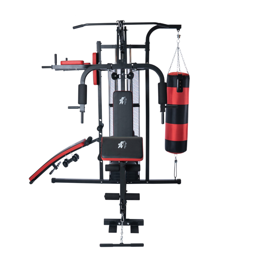
ELITE GAIN TF-7005
Please Keep For Future Reference
HJ-8TCD-IXQ6
IMPORTANT - Please Read Instructions Fully Before Assembly Or Use
These instructions contain important information which will help you get the best
from your equipment and ensure safe and correct assembly, use and maintenance.
If you need help or have damaged or missing parts,
call the Customer Helpline: 0330 124 0718 (Opening hours: Mon-Fri 9:00am-3:00pm)
or Email: customerservices@fit4home.co.uk
1
Advertisement
Table of Contents

Related Manuals for Fit4Home ELITE GAIN TF-7005


Summary of Contents for Fit4Home ELITE GAIN TF-7005
- Page 1 USER MANUAL ELITE GAIN TF-7005 Please Keep For Future Reference HJ-8TCD-IXQ6 IMPORTANT - Please Read Instructions Fully Before Assembly Or Use These instructions contain important information which will help you get the best from your equipment and ensure safe and correct assembly, use and maintenance.
-
Page 2: Table Of Contents
CONTENTS Safety Information Parts List 04-05 Exploded Diagram Assembly Instructions 07-18 Step 1 Step 2 Step 3 Step 4 Step 5 Step 6 Step 7 Step 8 Step 9 Step 10 Step 11 Step 12 Step 13 Exercises 19-20 Declaration... -
Page 3: Safety Information
IMPORTANT SAFETY INFORMATION PLEASE KEEP THIS MANUAL IN A SAFE PLACE FOR REFERENCE It is important to read this entire manual before assembling and using the equipment. Safe and efficient use can only be achieved if the equipment is assembled, maintained and used properly. -
Page 4: Parts List
PARTS LIST Description Quantity Description Quantity Main Base Tube Front Bottom Tube Middle Bottom Tube Rear Base Tube Weight Slider Rod Locating Tube Weight Pick Up Pole Left Support Tube Rear Beam Tube Right Side Support Tube(Up) Right Side Support Main Support Tube Tube(Down) Top Brace Tube... - Page 5 PARTS LIST Selector Pin Locating Pin Press Pin Ф12 Washer M10 Knob Small Bearing Boxing Bag Dumbbell Hook M8x20 Knob M12x35 Knob Cover Holder Protecion Cover Hook Chain Carriage Bolt T Type Supporting M10x60l Plate Weight Plate Weight Stack Top Plate Rubber Washer 50x50mm Tube...
- Page 6 EXPLODED DRAWING...
-
Page 7: Assembly Instructions
ASSEMBLY INSTRUCTIONS STEP 1 Place the Main base tube (1) flat on the floor, connecting the bottom of the tube (3) and the back end of the tube (4) with 2*M10*70 bolt (28).2*bolt M10*70(28), 4 x Ø10 washer(33) and 2x M10 nut (34 NEEDS DIAGRAM IMAGE STEP 2 Insert the weight slider rod (5) to the... -
Page 8: Step 3
ASSEMBLY INSTRUCTIONS STEP 3 The left support tube (8) and the right support tube (down) (11) are installed on the middle bottom tube (3). Tighten 2*M10*70 bolt (28)4* Ø10 washer (33)2*M10 nut (34). Insert the right support tube (up) (10) to the right support tube (down)(11). Tighten 2*M10*60 bolt (30)4* Ø10 washer (33)2*M10 nut (34). -
Page 9: Step 4
ASSEMBLY INSTRUCTIONS STEP 4 Install the main support tube (12) to the main base tube (1).Tighten 2*M10*70 bolt (28)4* Ø10 washer (33)2*M10 nut (34). Connecting the upper beam (13) and the main support tube (12) Tighten 2*M10*70 bolt (28)4* Ø10 washer (33)2*M10 nut (34). Then the upper beam (13) is mounted on the rear cross member (9).Tighten 2*M10*70 bolt (28)4* Ø10 washer (33)2*M10 nut (34). -
Page 10: Step 5
ASSEMBLY INSTRUCTIONS STEP 5 The support arm (left) (24) and a supporting arm (right) (25) is connected with the left support tube (8)Tighten 2*M10*70 bolt (28) 4* Ø10 washer (33)2*M10 nut (34). Fixed the samll back cushion(89) and left support tube(up)(8)with 2pcs M10*65 bolt(29) and 2pcs Ø10 washer (33). -
Page 11: Step 6
ASSEMBLY INSTRUCTIONS STEP 6 The inclined support pipe (20) is mounted on the main base tube (1).Tighten 2*M10*60 carriage bolt (65)2* Ø10 washer (33)2*M10 nut (34). The seat tube (19) is assembled on the main support tube (12) Tighten 2*M10*70 bolt (28)4* Ø10 washer (33)2*M10 nut (34) Then the seat tube (19) connected with the oblique support tube (20) Tighten 2*M10*60 carriage bolt (65)2* Ø10 washer (33)2*M10 nut (34). -
Page 12: Step 7
ASSEMBLY INSTRUCTIONS STEP 7 1. The butterfly arm bracket (15) is mounted on the upper beam (13). Insert M12*130 bolt (36) 4*bearing (56) and 2xØ12washer(37)tighten with M12 nut(38). Install butterfly arm (16, 17) to the butterfly arm bracket (15) fixed by 2*bearing(56) and Ø12washer(37)tighten with M12 nut(38). - Page 13 ASSEMBLY INSTRUCTIONS STEP 8 Let cable A goes through pulley B (76) first, then fixed the pulley housing (77) pulley B (76) and top brace tube (12) with M10*45 bolt and M10 nut.Let cable A goes through the pulley of main support tube (12),over pulley connecting plate (48) ,goes up through the pulley (75) on the top brace tube(12) And then through the net cover plate (61)Ф12 washer (54)Fixed in the selector lever (7) tighten all pulleys with M10*45 bolt(31) and M10 nut(33).
-
Page 14: Step 9
ASSEMBLY INSTRUCTIONS STEP 9 Fixed the single pulley bracket (47) and main support tube(12) with M10*60 bolt(30)4* Ø10 washer (33)2*M10 nut (34). Fixed one end of cable C and butterfly arm L (16) with M8*20 bolt(40) M8 nut(43). Let cable C goes through single pullley bracket(47),then double pulley bracket (49) ,fixed them with M10*40 bolt;... -
Page 15: Step 10
ASSEMBLY INSTRUCTIONS STEP 10 Let cable B goes through pulley of leg developer first and the pulley of main support tube. Then goes through as shown as the drawing connected with Hook and chain. -
Page 16: Step 11
ASSEMBLY INSTRUCTIONS STEP 11 The 4 pieces of net cover sheet (62) arranged in the net cover plate frame (61) and fixed by a positioning tube (6) 2*M8*15 (41) and tighten the bolts. -
Page 17: Step 12
ASSEMBLY INSTRUCTIONS STEP 12 Put on the back board (26)With the Locating pin(52)Fixed on the left support tube (8) Insert the foam tube (23) through the left support tube (8) Put on the foam (101) both ends of the foam tube (23). Put on the dumbbell (96) to the main frame supine hook (26)Insert the long foam tube (27) through the main frame (26) supine Put on the handle cover (79) from the two ends of long foam tube (27). -
Page 18: Step 13
ASSEMBLY INSTRUCTIONS STEP 13 The boxing bag (57) is mounted on the right side of the tube (upper)(10) and is connected with an annular hook (63) and a pull rope (98). Connected lat pull bar(92) and cable A(93) with hook(63) Connected T-bar(91) and cable B(94) with 2 hooks(63)and chain(64). - Page 19 EXERCISE INSTRUCTION Low Pulley Row Knee Raise Bicep Curls (Trapezius-Latissimus (Hit Flexors-Rectus Abdominis)Fit (Biceps-Forearm Flexors) Dorsierectorspinaf) “T”-Bar To Low Pulley Lie On Your Fit “T”-Bar To Low Pulley Grip Fit “T”-Bar To Low Pulley Sit With Back With Legs Almost Straight Curl The Bar And Stand With Your Feet Against Cross-Brace.
- Page 20 EXERCISE INSTRUCTION Leg Curl Leg Extensions Crunches (Hamstring Group) (Quadriceps) (Rectus Abdominis-Serratus-Lower This Exercise Is Preformed With One Fit The Roll Pads To The Bottom Hole. Latissi-Mus Dorsi) Fit “T” Bar To High Leg At A Time. Fit The Roll Pads To The Hook Your Legs Around The Roll Pads Pulley And Roll Pads To Bottom Hole.
-
Page 21: Declaration
Declaration of Conformity We, Importer Fit4home Ltd Unit A, Perseverance Mills, Olive Lane, Darwen BB3 3DQ United Kingdom Declare that the product TF-7005 Home Gym Complies with the essential health and safety requirements of the following directive: Direction for 2014/357/EU for Stationery training equipment...
Need help?
Do you have a question about the ELITE GAIN TF-7005 and is the answer not in the manual?
Questions and answers