Table of Contents
Advertisement
Assembly instructions
DE
ACHTUNG! WICHTIGE SICHERHEITSANWEISUNGEN!
Den Hinweisen auf Seite 3 dieser Montageanleitung ist Folge zu
leisten.
GB
ATTENTION! IMPORTANT SAFETY INFORMATION!
Follow the instructions on page 3 of this manual.
FR
ATTENTION! IMPORTANTES INDICATIONS DE SÉCURITÉ!
Les instructions de la page 3 de cette notice de montage doivent
être observées strictement.
NL
LET OP! BELANGRIJKE VEILIGHEIDSINSTRUCTIES!
Volg de instructies op pagina 3 van deze montagehandleiding
op.
IT
ATTENZIONE! INDICAZIONI SULLA SICUREZZA
IMPORTANTI!
Prestare attenzione alle note alla pagina 3 delle presenti
istruzioni di montaggio.
ES
ATENCION INDICACIONES IMPORTANTES DE SEGURIDAD!
Deben seguirse las indicaciones detalladas en página 3 de
estas instrucciones de montaje.
Nastavitve str 43 in 45.
Pazi v angleščini so druge kratice
na ekranu.
Glej tudi kratka navodila!
Installation, commissioning, utilization and maintenance
TST FUZ2
Versions:
-A/ -B/ -C/ -CX /
-CGH / -CXGH
/ -LGH
Attention
Important Safety
Information
These instructions must
be observed to ensure
personal safety.
Store these instructions
safely.
Advertisement
Table of Contents

Related Manuals for Feig Electronic TST FUZ2-A


Summary of Contents for Feig Electronic TST FUZ2-A
- Page 1 Nastavitve str 43 in 45. Pazi v angleščini so druge kratice na ekranu. Glej tudi kratka navodila! Assembly instructions Installation, commissioning, utilization and maintenance Attention TST FUZ2 Important Safety Versions: Information -A/ -B/ -C/ -CX / -CGH / -CXGH These instructions must / -LGH be observed to ensure personal safety.
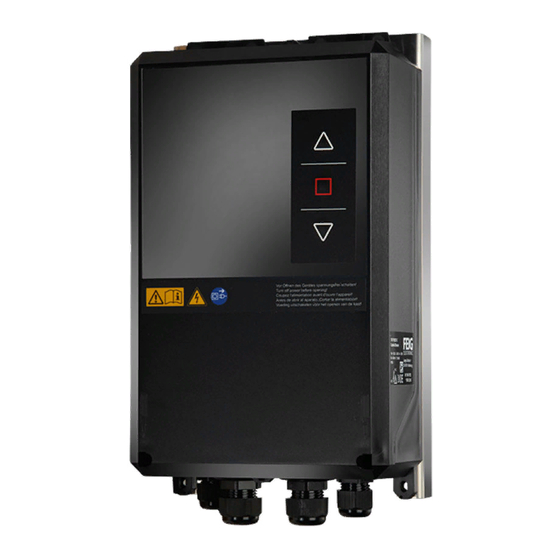
- Page 2 This Manual is directed especially at persons involved with commissioning the TST FUZ2 door controller of FEIG ELECTRONIC GmbH. The installation and commissioning of the controller shall only be carried out by officially trained electrical experts who are familiar with the safety standards of electrical drive and automation technology.
-
Page 3: General Information About This Document
General information about this document Language of the original operating instructions: German The functional description employs the following characters to indicate the different danger areas and useful tips. ATTENTION points out information which is IMPORTANT indicates a risk to persons if the procedure is not to the operation of the door controller and/or the carried out as described. -
Page 4: Notes
Para la seguridad de las personas es importante seguir estas indicaciones. Deben guardarse estas indicaciones. Puede encontrar estas instrucciones de montaje en el área de descarga en www.feig.de. Se ruega iniciar sesión con los siguientes datos de acceso: Nombre de usuario: Download / Password: feig FEIG ELECTRONIC GmbH Page 2 of 71 FUZ2-A-B-C-CX-L_Montageanleitung_GB_10.docx... - Page 5 Assembly Instructions FUZ2-A/-B/-C/-CX/-L Download feig FEIG ELECTRONIC GmbH Page 3 of 71 FUZ2-A-B-C-CX-L_Montageanleitung_GB_10.docx...
-
Page 6: Table Of Contents
Mechanical limit switches ......................27 Photo eye ............................ 28 External triggering devices ....................... 28 5.10 Traffic light connection ......................29 5.11 Overview of outputs ........................30 5.12 Overview of inputs ........................31 FEIG ELECTRONIC GmbH Page 4 of 71 FUZ2-A-B-C-CX-L_Montageanleitung_GB_10.docx... - Page 7 Pre-limit switch setting ......................50 10.4 Ramp configuration ........................50 10.5 Correction of the final positions ....................50 Functions Messages 12.1 Error messages .......................... 51 12.2 Information messages ....................... 61 General messages Specifications Directives and Standards FEIG ELECTRONIC GmbH Page 5 of 71 FUZ2-A-B-C-CX-L_Montageanleitung_GB_10.docx...
-
Page 8: General Description And Intended Use
TST SRA: connectable module auxiliary relay TST LCD / clear text: Clear text display with 2x16 signs. Evaluation of interface signals for remote control, diagnosis and configuration of the parameters of the door FEIG ELECTRONIC GmbH Page 6 of 71 FUZ2-A-B-C-CX-L_Montageanleitung_GB_10.docx... -
Page 9: Safety Information
The manufacturer has carefully checked and inspected the hardware and software, but no warranty is given for a complete absence of errors. Dispose of the product at the end of its life cycle in accordance with the applicable statutory provisions. FEIG ELECTRONIC GmbH Page 7 of 71 FUZ2-A-B-C-CX-L_Montageanleitung_GB_10.docx... -
Page 10: Installation Of The Controller
Should cooling not be sufficient, an additional heat sink may be inserted between the controllers housing and the additional housing to dissipate the heat to the outside (see chapter 4.2 Additional heat sink for small housing). FEIG ELECTRONIC GmbH Page 8 of 71 FUZ2-A-B-C-CX-L_Montageanleitung_GB_10.docx... -
Page 11: Housing Options
-20°C 4.1 Housing option 1 / small housing This type of housing is used for controller types TST FUZ2-A, TST FUZ2-B, and -CX. The expansion card TST RFUxK can be used in this housing only in combination with controller type TST FUZ2-B. -
Page 12: Additional Heat Sink For Small Housing
The additional heat sink must have the following design: Figure 4: Additional heat sink FEIG ELECTRONIC GmbH Page 10 of 71 FUZ2-A-B-C-CX-L_Montageanleitung_GB_10.docx... - Page 13 Assembly instructions FUZ2 -A/-B/-C/-CX/-L The additional heat sink must be bolted to the housing and then controller can be installed: Figure 5: Drilling layout for additional heat sink and controller _10.docx FEIG ELECTRONIC GmbH Page 11 of 71 FUZ2-A-B-C-CX-L_Montageanleitung_GB...
- Page 14 Step 3: install the controller Step 2: remove the spacer Do not use spacers! All four screws must be completely recessed! Use the following screws: Use countersunk screw M4 DIN 965 _10.docx FEIG ELECTRONIC GmbH Page 12 of 71 FUZ2-A-B-C-CX-L_Montageanleitung_GB...
-
Page 15: Housing Option 2 / Large Housing
This type of housing is used for controller types TST FUZ2-CGH, TST FUZ2-B, and -LGH. Min. 100mm 89,5 Min. 100mm Floor Figure 6: Installation in large housing Figure 7: Drilling template large housing _10.docx FEIG ELECTRONIC GmbH Page 13 of 71 FUZ2-A-B-C-CX-L_Montageanleitung_GB... -
Page 16: Electrical Connection
_10.docx FEIG ELECTRONIC GmbH Page 14 of 71 FUZ2-A-B-C-CX-L_Montageanleitung_GB... -
Page 17: Power Supply Voltage Without Main Switch
L´ N´ N´ L´ CEE plug 3 poles, Fuse 16A / K- Type blue Figure 8: Connecting the power cable The power plug must be visible and accessible from the control system. _10.docx FEIG ELECTRONIC GmbH Page 15 of 71 FUZ2-A-B-C-CX-L_Montageanleitung_GB... -
Page 18: Power Supply Voltage With Main Switch
Assembly instructions FUZ2 -A/-B/-C/-CX/-L 5.2 Power supply voltage with main switch Sicherung 16A/K-Typ Figure 9: Connecting the power cable FEIG ELECTRONIC GmbH Page 16 of 71 FUZ2-A-B-C-CX-L_Montageanleitung_GB_10.docx... -
Page 19: Motor And Brake
In the case of drive units with an electronic brake, ensure that the brake is equipped with adequate suppression. We recommend the use of RC-elements for interference suppression purposes. For the relay K2 to work as a brake relay, set parameter P.702 = 3201. _10.docx FEIG ELECTRONIC GmbH Page 17 of 71 FUZ2-A-B-C-CX-L_Montageanleitung_GB... -
Page 20: Safety Edge On The Integrated Evaluation
8,2K 1,2K 61 - 62 Junction brown white green Spiral cable 41 42 Receiver Slack rope optional slip switch door switch Transmitter Figure 11: Connection of an optical safety edge FEIG ELECTRONIC GmbH Page 18 of 71 FUZ2-A-B-C-CX-L_Montageanleitung_GB_10.docx... -
Page 21: Electrical Resistance Safety Edge
8,2K 1,2K 61 - 62 Junction Spiral cable 43 44 41 42 Slack rope optional slip switch door switch Outside Inside white brown Figure 12: Connecting an electrical resistance - safety edge _10.docx FEIG ELECTRONIC GmbH Page 19 of 71 FUZ2-A-B-C-CX-L_Montageanleitung_GB... -
Page 22: Safety Edge At The 2Nd Integrated Evaluation (Input 10)
Assembly instructions FUZ2 -A/-B/-C/-CX/-L 5.5 Safety edge at the 2nd Integrated evaluation (input 10) The evaluation / input is not available for variant TST FUZ2-A! Various types of safety edges can be connected, for example: Dynamical optical system ... -
Page 23: Electrical Resistance Safety Edge
Jumper J 801 is located to the left and behind terminal 51 - 52 digital 1,2K 8,2K J801 = 3-4 Parameter P.5A2 = 0 Figure 15: Connecting an electrical resistance - safety edge _10.docx FEIG ELECTRONIC GmbH Page 21 of 71 FUZ2-A-B-C-CX-L_Montageanleitung_GB... -
Page 24: Light Curtain Tst Lgb
Electronic limit switch Encoder cable 4 wires Junction Blanked out by door Control cable 7 wires OUT1: Danger zone Door controller OUT2: Object zone Figure 16: Installation of the TST LGB _10.docx FEIG ELECTRONIC GmbH Page 22 of 71 FUZ2-A-B-C-CX-L_Montageanleitung_GB... -
Page 25: Connection Of The Tst Lgb
Pin 2 - white M12 /4 pole M12 /8 pole IMPORTANT! Female Female These wires connect M12 /8 pole M12 /4 pole with each other Male Male Figure 17: Connection of the TST LGB _10.docx FEIG ELECTRONIC GmbH Page 23 of 71 FUZ2-A-B-C-CX-L_Montageanleitung_GB... -
Page 26: Limit Switchconnection
5 6 7 8 9 10 111213 Safety edge Jumper 7 8 9 10 RS485-B RS485-A +12 VDC Emergency stop Emergency stop Figure 18: Absolute encoder TST PE / TST PE FSB _10.docx FEIG ELECTRONIC GmbH Page 24 of 71 FUZ2-A-B-C-CX-L_Montageanleitung_GB... -
Page 27: Absolute Encoder Tst Pd
4 poles M8 4-pole Min. IP65, gold socket plated contacts Wire 3: blue Wire 2: white Wire 4: black Wire 1: brown shield / PE Figure 19: Absolute encoder TST PD _10.docx FEIG ELECTRONIC GmbH Page 25 of 71 FUZ2-A-B-C-CX-L_Montageanleitung_GB... -
Page 28: Absolute Encoder Des
Wire 3: GND à Terminal 34 Wire 4: Channel A à Terminal 32 Wire 5: Emergency stop à Terminal 33 Wire 6: 12 VDC Figure 20: Connection of absolute encoder DES _10.docx FEIG ELECTRONIC GmbH Page 26 of 71 FUZ2-A-B-C-CX-L_Montageanleitung_GB... -
Page 29: Mechanical Limit Switches
OPEN Crank switch CLOSE 32* - E-stop 2 31* - E-stop 2 Emergency stop circuit Figur 21: Connecting cam switches Alternately, the pre-limit switches can also be connected as normally closed contacts. FEIG ELECTRONIC GmbH Page 27 of 71 FUZ2-A-B-C-CX-L_Montageanleitung_GB_10.docx... -
Page 30: Photo Eye
Assembly instructions FUZ2 -A/-B/-C/-CX/-L 5.8 Photo eye +24V Input 5 Receiver photo eye Figure 22: Photo eye connection 5.9 External triggering devices Figure 23: External triggering devices FEIG ELECTRONIC GmbH Page 28 of 71 FUZ2-A-B-C-CX-L_Montageanleitung_GB_10.docx... -
Page 31: Traffic Light Connection
10 1112 20 2122 Jumper blue Figure 24: Traffic light connection When a motor brake is being used, relay K2 is already occupied and it can not be used to control a traffic light. _10.docx FEIG ELECTRONIC GmbH Page 29 of 71 FUZ2-A-B-C-CX-L_Montageanleitung_GB... -
Page 32: Overview Of Outputs
L´ Door is Door is OPEN CLOSE CEE plug 3 poles,blue Fuse 16A / K- Type Figure 25: Overview of outputs Contrary to the mentioned standard settings, the relay function is selectable FEIG ELECTRONIC GmbH Page 30 of 71 FUZ2-A-B-C-CX-L_Montageanleitung_GB_10.docx... -
Page 33: Overview Of Inputs
Figure 26: Overview of inputs On the control option –B, input 10 is used as a second safety edge monitor. For the connection of mech. limit switches, please refer to section5.7.4 Mechanical limit switches. _10.docx FEIG ELECTRONIC GmbH Page 31 of 71 FUZ2-A-B-C-CX-L_Montageanleitung_GB... -
Page 34: Optional Plug-In And Expansion Cards
Several slots are available to expand the operation of the controller with optional plug-in and expansion cards. 6.1 Wireless receiverTST SFFE Figure 27: Wireless plug-in receiver To enable the slot for the wireless receiver, parameter P.802 must be set to 0202. _10.docx FEIG ELECTRONIC GmbH Page 32 of 71 FUZ2-A-B-C-CX-L_Montageanleitung_GB... -
Page 35: Induction Loop Detector Tst Suvek
Loop 1 Loop 2 Figure 28: Detector card To activate the slot for the detector, parameter P.802 must be set to 0302. It is not possible to operate detector cards in version –A FEIG ELECTRONIC GmbH Page 33 of 71 FUZ2-A-B-C-CX-L_Montageanleitung_GB_10.docx... -
Page 36: Safety Edge Monitor Tst Sura
To activate the slot for the safety edge monitor, parameter P.802 must be set to 0101 for TST SURA-1 or 0106 for TST SURA-6. The operation of safety edge monitors is not possible in version –A _10.docx FEIG ELECTRONIC GmbH Page 34 of 71 FUZ2-A-B-C-CX-L_Montageanleitung_GB... -
Page 37: Expansion Card Rfuxk
Figure 30: TST RFUxK expansion card Activate the expansion card by setting the parameter P.800 to 5. The card can not be operated in the versions:–B, –CGH, –CXGH and –LGH. _10.docx FEIG ELECTRONIC GmbH Page 35 of 71 FUZ2-A-B-C-CX-L_Montageanleitung_GB... -
Page 38: Interface Card Tst Rfuxfcom
With these , for example, it is possible to establish connections with partner controller or to a remote TST RFUxK board. Figure 31: Interface card TST RFUxFCOM The interface card cannot be used in version –A _10.docx FEIG ELECTRONIC GmbH Page 36 of 71 FUZ2-A-B-C-CX-L_Montageanleitung_GB... -
Page 39: Auxiliary Relay Tst Sra
The function of the associated output 2A may be adjusted by the parameter P.D0A. Figure 32: Auxiliary relay TST SRA The additional relay TST SRA cannot be used in version –A. _10.docx FEIG ELECTRONIC GmbH Page 37 of 71 FUZ2-A-B-C-CX-L_Montageanleitung_GB... -
Page 40: Lcd Text Display
Alternatively, controller TST FUZ2 may be expanded by a LCD text display. This provides more information at a glance. The display must not be enabled via a parameter. Figure 33: LCD text display The text display cannot be used in version –A _10.docx FEIG ELECTRONIC GmbH Page 38 of 71 FUZ2-A-B-C-CX-L_Montageanleitung_GB... -
Page 41: General Operating Instructions To Set Parameters
Use the arrow keys to select the required parameter. P: Offenhalt1 P.010 010= 10 s ATTENTION Not all the parameters are visible or may be changed immediately; this always depends on the password and the type of position set. _10.docx FEIG ELECTRONIC GmbH Page 39 of 71 FUZ2-A-B-C-CX-L_Montageanleitung_GB... -
Page 42: Editing A Selected Parameter
999= 0001 # parameter must be set for this: P.999 = 2 (extended commissioning mode) P: Password 0001 999= 0001# P: Password 999= 0002?# P: Password P.999 999= 0002# FEIG ELECTRONIC GmbH Page 40 of 71 FUZ2-A-B-C-CX-L_Montageanleitung_GB_10.docx... -
Page 43: Basic Settings
P.205: 0300 = Absolute encoder DES-A (GfA) P.205: 0700 = Absolute encoder DES-B (Kostal) P.205: 0800 = Absolute encoder TST PD / TST PE (FEIG) P.205: 0900 = Timer limit switches FEIG ELECTRONIC GmbH Page 41 of 71 FUZ2-A-B-C-CX-L_Montageanleitung_GB_10.docx... - Page 44 The automatic query of basic data can be interrupted by pressing the OPEN button when the controller is being turned ON. This causes a direct jump to the parameter configuration mode. _10.docx FEIG ELECTRONIC GmbH Page 42 of 71 FUZ2-A-B-C-CX-L_Montageanleitung_GB...
-
Page 45: Startup
Zu pos. OK Door opens. Now press , repeat the process until the correction travel has I.515 Correc. Fahrt been completed. (Message I.510 = OK) I.510 Korrek. OK Tor öffnet Tor schließt _10.docx FEIG ELECTRONIC GmbH Page 43 of 71 FUZ2-A-B-C-CX-L_Montageanleitung_GB... -
Page 46: With Mechanical Limit Switches
To prevent the door from moving unintentionally, adjust the limit switches only when the Emergency-STOP is activated or with the controller turned off ! The door may now be operated in automatic mode. _10.docx FEIG ELECTRONIC GmbH Page 44 of 71 FUZ2-A-B-C-CX-L_Montageanleitung_GB... -
Page 47: With Light Curtain Tst Lgb
The display shows the messages in alternation: The door was I.515 xxx Start mit recognized in the CLOSE position and the light rays were taught- in correctly. !Korrekturfahrt! I.610 I615 LL Abgl. ok _10.docx FEIG ELECTRONIC GmbH Page 45 of 71 FUZ2-A-B-C-CX-L_Montageanleitung_GB... - Page 48 P.275: Correction of increments after conclusion of the synchronization -> recommended as fine setting for the end position BELOW. The value set here must NOT be re-set after the new teach-in of all end positions. _10.docx FEIG ELECTRONIC GmbH Page 46 of 71 FUZ2-A-B-C-CX-L_Montageanleitung_GB...
-
Page 49: Renewed Request For "Learning" Limit Positions
You can use diagnostic parameter P.910 = 2 to display the actual motor current. The boost should be set so that the motor current remains as low as possible. _10.docx FEIG ELECTRONIC GmbH Page 47 of 71 FUZ2-A-B-C-CX-L_Montageanleitung_GB... -
Page 50: Movement Optimisation For The Door
At this point it reduces the speed of the door to creep speed using ramp "r2”. The door now moves at creep speed until the limit switch OPEN is reached. At this point the door is stopped (ro). _10.docx FEIG ELECTRONIC GmbH Page 48 of 71 FUZ2-A-B-C-CX-L_Montageanleitung_GB... -
Page 51: Closing Of The Door
At this point it reduces the speed of the door to creep speed using ramp "r6”. The door now moves at creep speed until the limit switch CLOSE is reached. At this point the door is stopped (ru). _10.docx FEIG ELECTRONIC GmbH Page 49 of 71 FUZ2-A-B-C-CX-L_Montageanleitung_GB... -
Page 52: Pre-Limit Switch Setting
Changing in the negative direction causes a shift towards the bottom. 11 Functions You will find an overview of Parameters of this assembly instruction and there description in the added document "Parameter list TST FUZ2" _10.docx FEIG ELECTRONIC GmbH Page 50 of 71 FUZ2-A-B-C-CX-L_Montageanleitung_GB... -
Page 53: Messages
• Too much „pancaking“ when starting, brake releases too soon, or too little torque, adjust boost (P.140 or P.145) as necessary. • Fault on the position transmitter F.033 Bad position transmitter protocol • No position data available over an extended period FEIG ELECTRONIC GmbH Page 51 of 71 FUZ2-A-B-C-CX-L_Montageanleitung_GB _10.docx... - Page 54 • Dynamical optical safety edge connected but not set in Parameter P.460 • Connection cable defective or not connected F.363 Interruption on edge input • Termination resistor incorrect or missing • Jumper 1K2 / 8K2 incorrectly set FEIG ELECTRONIC GmbH Page 52 of 71 FUZ2-A-B-C-CX-L_Montageanleitung_GB _10.docx...
- Page 55 • The slip door was not fully opened or closed door switch on the internal safety edge evaluation unit channel 1 • Short circuit detected on edges with normally closed contact F.380 Short circuit detected on safety input FEIG ELECTRONIC GmbH Page 53 of 71 FUZ2-A-B-C-CX-L_Montageanleitung_GB _10.docx...
- Page 56 • Wrong motor data set (P.100 – P.103) F.410 Over-current (motor current or DC- • Non-adjusted voltage increase / boost set bus) (P.140 or P.145) • Motor not properly dimensioned for door • Door sticks FEIG ELECTRONIC GmbH Page 54 of 71 FUZ2-A-B-C-CX-L_Montageanleitung_GB _10.docx...
- Page 57 • When 24V is shorted the controller voltage does not ramp up and glow lamp V306 comes on. • The incoming mains supply for the Controller is to high F.525 Overvoltage at the incoming mains • The incoming mains supply fluctuates very extremly supply FEIG ELECTRONIC GmbH Page 55 of 71 FUZ2-A-B-C-CX-L_Montageanleitung_GB _10.docx...
- Page 58 • The simulated end switch OPEN was not reached at the expected position F.702 OPEN Position not found in timer • The tolerance band for the recognition time is to small (P.239) mode FEIG ELECTRONIC GmbH Page 56 of 71 FUZ2-A-B-C-CX-L_Montageanleitung_GB _10.docx...
- Page 59 F.80A Wrong Test of input A of the • The device which is connected to the input does not work correct stationary unit TST FSx • The stationary unit is defective FEIG ELECTRONIC GmbH Page 57 of 71 FUZ2-A-B-C-CX-L_Montageanleitung_GB _10.docx...
- Page 60 • The connected optical safety edge is faulty F.841 Frequency error on input 1 of mobile unit • The connected optical safety edge is faulty F.843 Frequency error on input 3 of mobile unit FEIG ELECTRONIC GmbH Page 58 of 71 FUZ2-A-B-C-CX-L_Montageanleitung_GB _10.docx...
- Page 61 ROM error on extension board • Defective hardware or noise-saturated environment • Defective hardware or noise-saturated environment F.912 RAM error on extension board • Hardware defect F.920 Internal 2.5 V reference voltage incorrect FEIG ELECTRONIC GmbH Page 59 of 71 FUZ2-A-B-C-CX-L_Montageanleitung_GB _10.docx...
- Page 62 • The clock has an error → make a reset F.969 Internal error Real time clock • New EPROM version F.970 Plausibility parameter block error • Controller not yet initialized • Some parameter is implausible FEIG ELECTRONIC GmbH Page 60 of 71 FUZ2-A-B-C-CX-L_Montageanleitung_GB _10.docx...
-
Page 63: Information Messages
I.610 Light line alignment completed successfully. I.615 Light line alignment requested. I.620 Door in PU when syncing but some rays of light are still masked. Adjust P.446 door masking in PU! FEIG ELECTRONIC GmbH Page 61 of 71 FUZ2-A-B-C-CX-L_Montageanleitung_GB _10.docx... - Page 64 The radio connection interrupts during door drive for a short time. Possible causes are: • The Distance between mobile and stationary unit is larger than specified • No perfect Orientation of stationary and mobile antenna • The radio link is disturbed by external noise FEIG ELECTRONIC GmbH Page 62 of 71 FUZ2-A-B-C-CX-L_Montageanleitung_GB _10.docx...
-
Page 65: General Messages
Information messages during the parameter configuration: noEr Error memory: no error saved Er-- Error memory: if error but without associated message being found Prog Programming message while carrying out original parameter or default set _10.docx FEIG ELECTRONIC GmbH Page 63 of 71 FUZ2-A-B-C-CX-L_Montageanleitung_GB... - Page 66 Wireless Channel 1 E.402 Wireless Channel 2 Inductive loop E.501 Detector channel 1 E.502 Detector channel 2 E.503 Detector channel 3 E.504 Detector channel 4 Internal-Inputs E.900 Controller chip fault signal _10.docx FEIG ELECTRONIC GmbH Page 64 of 71 FUZ2-A-B-C-CX-L_Montageanleitung_GB...
- Page 67 Input 2 of mobile unit E.F03 Input 3 of mobile unit E.F04 Input 4 of mobile unit E.F0A Input A of stationary unit E.F0B Input B of stationary unit E.F0C Input C of stationary unit _10.docx FEIG ELECTRONIC GmbH Page 65 of 71 FUZ2-A-B-C-CX-L_Montageanleitung_GB...
-
Page 68: Specifications
24 VDC / min. 10 mA / max. 120 mA Generell application: All types of resistive, iinductive and For version –B/-C / -CX / -CGH / - capacitive loads in industrial applications CXGH / -LGH _10.docx FEIG ELECTRONIC GmbH Page 66 of 71 FUZ2-A-B-C-CX-L_Montageanleitung_GB... - Page 69 IP54 (only in respect of enclosure) Weight approx. 5 kg Equipment mobility: stationary Equipment type: Motor type external motor is not part of the delivery from FEIG ELECTRONIC GMBH Protection class: Protection class I _10.docx FEIG ELECTRONIC GmbH Page 67 of 71 FUZ2-A-B-C-CX-L_Montageanleitung_GB...
-
Page 70: Directives And Standards
EN 61000-6-4:2007 Electromagnetic radiation, industrial area Applied national specifications regarding EN 12453:2001 Safety in use of power operated doors - the above directives: Requirements • Chapter 5.2 Drive Systems and Power Supply _10.docx FEIG ELECTRONIC GmbH Page 68 of 71 FUZ2-A-B-C-CX-L_Montageanleitung_GB... - Page 71 Assembly instructions FUZ2 -A/-B/-C/-CX/-L _10.docx FEIG ELECTRONIC GmbH Page 69 of 71 FUZ2-A-B-C-CX-L_Montageanleitung_GB...
Need help?
Do you have a question about the TST FUZ2-A and is the answer not in the manual?
Questions and answers