Table of Contents
Advertisement
Quick Links
®
Installation, Operation and Maintenance Manual
Please read and save these instructions for future reference. Read carefully before attempting to assemble, install,
operate or maintain the product described. Protect yourself and others by observing all safety information. Failure
to comply with these instructions will result in voiding of the product warranty and may result in personal injury
and/or property damage.
IMPORTANT: DS-M fans must be installed with the supplied CAT-5e communication cable or shielded CAT-5e
(by others) that complies with the following specifications. Cable must be twisted pair, shielded 26 ga. CAT-5e
cable with a drain wire and must be compliant with ISO 11801. Cable must use shielded RJ45 connectors with
a soldered drain and wiring configuration must follow EIA/TIA T568B wiring pinout. Individual CAT-5e cable
lengths must not exceed 200 ft. in order to prevent network communication issues.
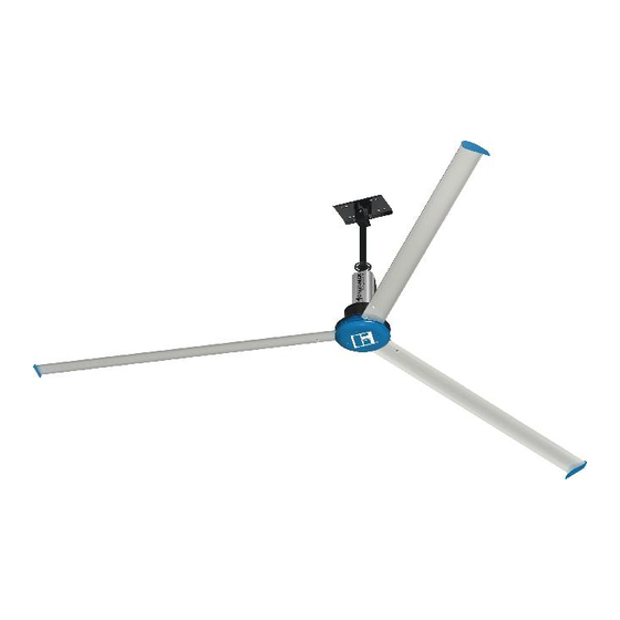
Model DS-M is the ideal choice for providing year-round comfort in air circulation and destratification applications.
Featuring an aerodynamic, extruded aluminum airfoil design and a high efficiency direct drive motor, model DS-M
delivers maximum airflow at a fraction of the operating cost of other HVLS fans. And, with its universal ceiling mount,
the DS-M fan is the easiest HVLS fan to install in the market!
General Safety Information
IMPORTANT: To reduce the risk of fire, electric shock,
or injury to persons, Model DS-M fans must be installed
with a mount assembly, motor assembly and airfoils that
are marked (on their cartons) to indicate suitability with
this model. Other mounts, motors, and airfoils cannot
be substituted.
WARNING
To reduce the risk of fire, electric shock, or injury to
persons, observe the following:
1. Use this unit only in the manner intended by the
manufacturer. If you have questions, contact the
manufacturer.
2. Before servicing or cleaning unit, switch
power off at service panel and lock the service
disconnecting means to prevent power from
being switched on accidentally. When the service
disconnecting means cannot be locked, securely
fasten a prominent warning device, such as a tag,
to the service panel.
®
High Volume, Low Speed Ceiling Fans
WARNING
To reduce the risk of fire, electric shock, or injury to
persons, observe the following:
1. Installation work and electrical wiring must be
done by qualified person(s) in accordance with all
applicable codes and standards, including fire-
rated construction.
2. When cutting or drilling into wall or ceiling, do
not damage electrical wiring and other hidden
utilities.
WARNING
This appliance can be used by children aged from 8
years and above and persons with reduced physical,
sensory or mental capabilities or lack of experience
and knowledge if they have been given supervision or
instruction concerning use of the appliance in a safe
way and understand the hazards involved. Children
shall not play with the appliance. Cleaning and user
maintenance shall not be made by children without
supervision.
High Volume, Low Speed Ceiling Fans
Document 484698
Model DS-M
1
Advertisement
Table of Contents

Related Manuals for Greenheck DS-M


Summary of Contents for Greenheck DS-M
-
Page 1: General Safety Information
200 ft. in order to prevent network communication issues. Model DS-M is the ideal choice for providing year-round comfort in air circulation and destratification applications. Featuring an aerodynamic, extruded aluminum airfoil design and a high efficiency direct drive motor, model DS-M delivers maximum airflow at a fraction of the operating cost of other HVLS fans. - Page 2 Only qualified personnel should install this fan. shipment(s) must be limited to only items on the bill of Personnel should have a clear understanding of these lading. instructions and should be aware of general safety Storage precautions. Improper installation can result in electric Fans are protected against damage during shipment.
-
Page 3: Table Of Contents
Table of Contents Removing from Storage As fans are removed from storage to be installed in their General Safety Information ....1 final location, they should be protected and maintained General Information . -
Page 4: General Information
General Information to alert personnel of the overhead location of the fan(s). Pre-Installation Checks 10. Before installation, it is important to verify that the IMPORTANT: Consult all applicable national, state mounting surface will bear the operating weight and local codes to ensure that all necessary code and maximum torque (twisting force) of the unit. -
Page 5: Fan Components
Fan Components NOTE: Additional parts (provided by others) may be Verify that all of the following parts and hardware have been received prior to beginning installation. required to complete the fan installation, including ® Contact your local representative or the manufacturer if additional wiring, steel angle or Unistrut channel, and replacement parts are required. -
Page 6: Optional Fan Components
(BY OTHERS) The following tools will be required to complete the • Magnetic Nut Driver Extension installation of every DS-M fan. Additional tools may be NOTE: Model DS-M fan components can weigh 90 lbs. required depending on the application and installation or greater depending upon the fan size and accessories location of the fan. -
Page 7: Mounting Installation
Mounting Installation DANGER 1/2 in. - 13 X 2-1/2 in. GRADE 8 HEX BOLT Always disconnect, lock and tag power source before STEEL BEAM installing or servicing. Failure to disconnect power TORQUE TO 45 FT LBF source can result in fire, shock or serious injury. (61.0 N m) The following mounting installations are covered in this I-BEAM CLAMPING PLATE... - Page 8 Hardware/Tools Needed (Not Included): STRUCTURAL STEEL ANGLES (BY OTHERS) STEEL TRUSS / BAR JOIST • 1/2 in. – 13 Grade 8 Hex Bolt (4), length determined by wood beam thickness • Torque Wrench TORQUE TO 80 FT LBF • 3/4 in. Socket and Wrench (108.5 N m) STRUCTURAL STEEL ANGLES (BY OTHERS)
- Page 9 4. Torque hardware to 80 ft∙lbf (108.5 N∙m). Z-PURLIN TORQUE TO 80 FT LBF (108.5 N m) 5. Turn to page 10 to continue with Motor/Hub to Downtube Installation. Z-PURLIN BRACKET 1/2 in. - 13 x 1-3/4 in. GRADE 8 HEX BOLT Z-Purlin Mounting Kit 1/2 in.
-
Page 10: Motor/Hub To Downtube Installation
Motor/Hub to Downtube Installation Components required from Bag # 915065: • Motor/Hub Assembly (1) DOWNTUBE & MOUNT ASSEMBLY • Rear VFD Cover (1) • 3/8 in. – 16 x 23/4 in. Grade 8 Hex Bolt (2) LIGHT POWER PLUG (OPTIONAL) LIGHT COMMUNICATION PLUG •... -
Page 11: Fan Networking
Plug in the motor power, motor ground, and hall cables as shown. Note that the connectors on the “G” on the Greenheck logo closest to the motor (not Hall and motor power cables only fit in one specific critical for fan operation) orientation. - Page 12 All Remaining Fans FIRST FAN IN SERIES Modbus Address Settings - Dipswitch 3 Modbus Position Position Position Position Position Position Address 6, 7, 8 1. Remove the front VFD cover using a phillips screwdriver. ALL OTHER FANS IN SERIES 2. On the communication wiring terminal strip, remove the 24V (brown-white) wire and cap with a wire nut or heat shrink.
-
Page 13: Safety Retention Cable Installation
Safety Retention Cable Installation IMPORTANT: Do not put excessive tension on the safety retention cable during installation. The safety retention cable should be installed with a small amount of slack in the cable to ensure proper functioning. Do not allow the safety retention cable to contact any sharp edges. - Page 14 ® Gripple Hardware (Optional) Components required from Bag # 915067: ® • No. 4 Gripple Connector (1) Hardware/Tools (Not Included): • 1/16 in. Allen Wrench (optional) • Cable Cutters (optional) 1. From the top of the downtube, pull the safety retention cable until the cable is taut inside the downtube. 2.
-
Page 15: Guy Wire Installation
Guy Wire Installation IMPORTANT: Steel cable clamps consist of two parts: the u-bolt and the saddle. Steel cable clamps must be IMPORTANT: Guy wires must be installed 45º to 60º installed with the u-bolt over the dead-end of the guy from vertical to ensure proper functioning. - Page 16 ® Gripple Hardware (Optional) 4. Place a level against the downtube and tighten all (4) turnbuckles by hand in a crisscross pattern until IMPORTANT: Guy wires must be installed 45º to 60º the guy wires are tight and the fan is level. from vertical to ensure proper functioning.
-
Page 17: Airfoil Blade & Winglet Installation
Airfoil Blade & Winglet Installation IMPORTANT: Do not operate fans without the airfoil WARNING blades. Failure to comply with this warning will result To reduce the risk of personal injury, do not insert in voiding of the product warranty and may result in foreign objects in between rotating fan blades. -
Page 18: Wiring And Electrical - Factory Wiring Installation
(located at the top of the Installation downtube) and continue with the rest of the installation. IMPORTANT: DS-M fans must be installed with IMPORTANT: The fire alarm relay should only be the supplied CAT-5e communication cable or... - Page 19 IMPORTANT: Individual CAT-5e cable lengths must 2. Identify the desired location for installation of the fan control and run the remainder of the CAT-5e not exceed 200 ft. in order to prevent network control cable to this location. communication issues. 3.
-
Page 20: Pre-Start-Up Checks
Power Wiring Installation Electrical Plug Installation 1. Refer to the wiring diagrams below to complete DANGER power wiring. Always disconnect, lock and tag power source before 2. Secure any loose power cable to the building installing or servicing. Failure to disconnect power structure to ensure it does not interfere with fan source can result in fire, shock or serious injury. -
Page 21: Operation
Maintenance Verify that the fan is hanging so that the airfoils and downtube are level and the fan is plumb to NOTE: Installation and maintenance are to be the floor. Adjust guy wire tension as necessary (if performed only by qualified personnel who are familiar applicable). -
Page 22: Troubleshooting
Troubleshooting Each fan bears a manufacturer’s nameplate with the DANGER fan’s model number and a unique serial number for Disconnect and secure to the ‘OFF’ position all identification. This information will assist the local electrical power to the fan prior to inspection or representative and the manufacturer in providing service servicing. - Page 23 Modbus Registers The DS-M fan’s VFD is configured for Modbus RTU communication as standard. The Modbus register list is for applications where a building management system or field-supplied control are to be used for fan operation. Register Name R/W Retentive Signed Format...
-
Page 24: Maintenance Log
As a result of our commitment to continuous improvement, Greenheck reserves the right to change specifications without notice. Product warranties can be found online at Greenheck.com, either on the specific product page or in the literature section of the website at Greenheck.com/Resources/Library/Literature.
Need help?
Do you have a question about the DS-M and is the answer not in the manual?
Questions and answers