
Subscribe to Our Youtube Channel
Related Manuals for DART Controls 730 Control Series


Summary of Contents for DART Controls 730 Control Series
- Page 1 CONTROLS Instruction Manual Low Voltage DC Brushless Control Phone (317) 873-5211 P.O. Box 10 Fax (317) 873-1105 5000 W. 106th Street www.dartcontrols.com Zionsville, Indiana 46077 A-5-3780C LT117 (0615)
-
Page 2: Table Of Contents
Warranty Dart Controls, Inc. (DCI) warrants its products to be free from defects in material and workmanship. The exclusive remedy for this warranty is DCI factory replacement of any part or parts of such product which shall within 12 months after delivery to the purchaser be returned to DCI factory with all transportation charges prepaid and which DCI determines to its satisfaction to be defective. -
Page 3: Introduction
Introduction Dart Controls 730 Series is a family of general purpose brushless motor controls. These controls commutate power into standard 3 phase sensored brushless (BLDC) motors. The 730 Series uses DC power sources of 11 to 15VDC or 18 to 54VDC, including batteries of 12, 24, 36, and 48 volts. -
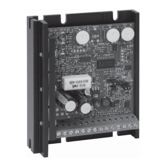
Page 4: Mounting Instructions And Dimensions
Mounting Instructions and Dimensions Six 3/16" wide slots are provided for control mounting (see dimension diagram below). Control chassis can be used as a template. Use standard hardware to mount. Caution: Do not mount where ambient temperature is outside range of -10 C (15 F) to 45 C (115... -
Page 5: Hook-Up Diagram
Hook-up Diagram Internal Fault LED 733BDC-CL ONLY P101 -3 -2 -1 -3 -2 -1 Power ON LED -1 -2 -3 -4 -5 -6 -7 -8 -9 -10 -11-12-13-14 HI W LO 10/12 AMP NORMAL BLOW Φ FUSE Φ Φ ON/OFF SWITCH BLDC MOTOR... -
Page 6: Hook-Up Procedure For Motors Without Timing Diagrams
Now apply power to the control. Slowly increase the speed by adjusting the Speed Pot clockwise. Watch for erratic rotation or excessive source current. If either occurs, immediately turn the Speed Pot counterclockwise to reduce speed, and turn off the power. Try a new phase line configuration, apply power and test again. -
Page 7: Speed Command Selection And Hook-Up
Inhibiting the Control The 730 series control has a ¼” spade pin (P7) on the control that can be used to inhibit the control. Tying this pin to the control common terminal (P1-6) will stop the control and override any other speed command. -
Page 8: Adjustments
Adjustments Current Limit Dart has factory set the Current Limit to 125% of 7.5 Amps DC. This setting should not need to be increased. If the current limit needs to be set to a lower value, do so by adjusting the Current Limit trimpot (CL) CCW until the desired setting is achieved. -
Page 9: Accel And Decel (733Bdc)
Accel and Decel (733BDC) Accel - The Accel trimpot is adjustable from 0-10 second of maximum output speed setting. The setting of the accel time is approximately proportional to the rotation of the Accel trimpot. As an example, a 50% setting of the Accel trimpot will result in approximately a 5 second linear accel ramp from zero to maximum speed. -
Page 10: Timing Diagram For 60° Motor
Timing Diagram for 60° Motor INPUT - 60 ELECTRICAL MOTOR SENSOR 3 (S3) TO TERMINAL P1-11 SENSOR 2 (S2) TO TERMINAL P1-10 SENSOR 1 (S1) TO TERMINAL P1-9 OUTPUT - 60 ELECTRICAL MOTOR PHASE 3 (θ3) TO TERMINAL P1-1 PHASE 2 (θ2) TO TERMINAL P1-3 PHASE 1 (θ1) TO TERMINAL P1-2... -
Page 11: Timing Diagram For 120° Motor
Timing Diagram for 120° Motor INPUT - 120 ELECTRICAL MOTOR SENSOR 1 (S1) TO TERMINAL P1-9 SENSOR 2 (S2) TO TERMINAL P1-10 SENSOR 3 (S3) TO TERMINAL P1-11 OUTPUT - 120 ELECTRICAL MOTOR PHASE 1 (θ1) TO TERMINAL P1-2 PHASE 2 (θ2) TO TERMINAL P1-3 PHASE 3 (θ3) TO TERMINAL P1-1... - Page 12 REPAIR PROCEDURE In the event that a Product manufactured by Dart Controls Incorporated (DCI) is in need of repair service, it should be shipped, freight paid, to: Dart Controls, Inc., 5000 W. 106th Street, Zionsville, IN. 46077, ATTN: Repair Department. Please include Name, Shipping Address (no P.O. Box), Phone Number and if possible, e-mail address.
Need help?
Do you have a question about the 730 Control Series and is the answer not in the manual?
Questions and answers