Table of Contents
Advertisement
Re-Order from
Omegamation
1-888-55-66342
1-888-55-66342
1-888-55-OMEGA
omegamation.com
LT125D (0408)
This datasheet has been downloaded from
CONTROLS
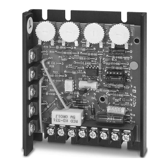
Instruction Manual
Variable Speed Control
TM
P.O. Box 10
5000 W. 106th Street
Zionsville, Indiana 46077
Phone (317) 873-5211
Fax (317) 873-1105
www.dartcontrols.com
http://www.digchip.com
at this
A-5-3262D
page
Advertisement
Table of Contents


Need help?
Do you have a question about the 125D Series and is the answer not in the manual?
Questions and answers