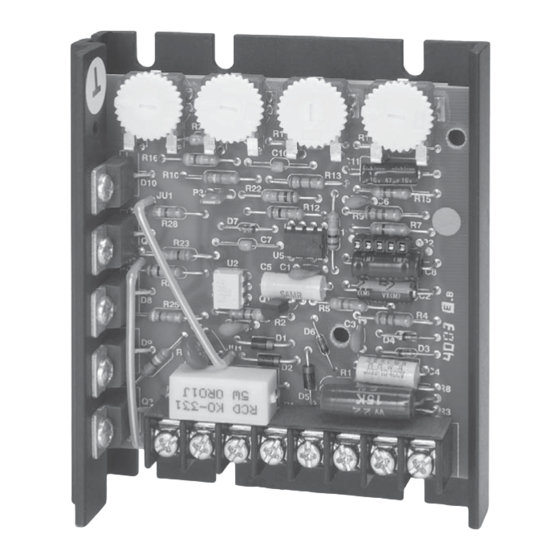
Summary of Contents for DART Controls 123D
- Page 1 CONTROLS Instruction Manual Variable Speed Control Phone (317) 873-5211 P.O. Box 10 Fax (317) 873-1105 5000 W. 106th Street www.dartcontrols.com Zionsville, Indiana 46077 LT114 (0713) A-5-3760B...
- Page 2 WARRANTY Dart Controls, Inc. (DCI) warrants its products to be free from defects in material and workmanship. The exclusive remedy for this warranty is DCI factory replacement of any part or parts of such product which shall within 12 months after delivery to the purchaser be returned to DCI factory with all transportation charges prepaid and which DCI determines to its satisfaction to be defective.
-
Page 3: Introduction
INTRODUCTION • The 123D variable speed control is available in a range of 150mA through 5.5 ADC (or up to 10 ADC if using a suitable external heatsink) at 24 through 36 VAC input. • The 125D variable speed control is available in a range of 150mA through 1/4 H.P. at 120/240 VAC input. -
Page 4: Mounting Procedure
---------- 15 AMP NOTE: To determine fusing for the 123D-C Series control (24 to 36 VAC input), use 200% of Full Load Current. TERMINAL STRIP WIRING INSTRUCTIONS The 125D Series uses an 8 position terminal strip for ease of connection. -
Page 5: D / 125D Hook-Up Diagram
3. For non-speedpot applications, the input connection to the LO, WIPER, and HI terminals must not be grounded! Serious control damage may result from a grounded input. 123D/125D HOOK-UP DIAGRAM Warning: Do not attempt to perform Hi-pot test across AC lines with control in circuit. -
Page 6: Trimpot Adjustment Chart & Procedure
NOTE: ADDITIONAL CUSTOMER HEATSINK REQUIRED FOR 125DV-C (120 VAC INPUT - GREATER THAN 1/2 H.P. MOTORS) AND (240 VAC INPUT - GREATER THAN 1 H.P. MOTORS). 125 EXTRUSION TEMPERATURES SHOULD NOT EXCEED 70 DEGREES C. NOTE: FOR DETERMINING TRIMPOT SETTINGS FOR THE 123D-C SERIES, SEE TRIMPOT SETTINGS PROCEDURE BELOW. TRIMPOT... -
Page 7: Control Modifications
CONTROL MODIFICATIONS TWO SPEED OPERATION DYNAMIC BRAKING Two pot operation is done using two 10K A DPDT switch is used to inhibit the control and to connect the ohm speed potentiometers in parallel (both DBR. Typical values for the DBR (dynamic brake resistor) are 5 HI's to P1-6, both LO's to P1-8). -
Page 8: Speedpot Kit Assembly
SPEEDPOT KIT ASSEMBLY CUSTOMER'S MOUNTING BRACKET DIALPLATE 2.00" dia. 1.240 .500 .370 .370 SPEEDPOT KNOB HEX NUT SPEEDPOT LO (CCW) (ORANGE) 1.250 SPEEDPOT WIPER (RED) SPEEDPOT HI (CW) (WHITE) .250 Dia. LOCK SPEEDPOT WASHER (5K 1/2W) .437 5/32 DIA. DIA. SPEEDPOT LOCATOR HOLE DIMENSIONS OPTION DESCRIPTIONS -1 option... -
Page 9: Options
-5 option Field or Factory Installed Isolated 4-20 ma.Signal Follower Available on Chassis Only* LINEARITY/GAIN ADJUSTMENT CURRENT SOURCE 250/500 -9 -10 (250G TERMINAL STRIP) -7 option Enclosed - Factory Installed only Isolated 4-20 ma. Signal Follower Chassis - Factory or Field Installed with Auto/Manual Switch Chassis - switch &... -
Page 10: Options
4) With power applied and a voltmeter monitoring motor output Vdc, apply 4mA to -5/-7 board. Check voltmeter reading and adjust the Linearity/gain trimpot, R16, on the -5/-7 board CCW until motor output voltage is less than 0.1Vdc. 5) Now apply 20mA to the -5/-7 board and adjust the Max trimpot to a voltage that is 5 volts (15 volts for the 250G series controls) above the fi... - Page 11 -55H option Isolated Signal Input Factory or Field Installed INPUT NOTE: This option cannot be used on the 123D-C series control. GAIN TYPE This option card allows for the use of either a grounded or non- SELECTOR VOLTAGE (Vin OR 4-20in)
-
Page 12: In Case Of Difficulty
Amps - DC output ............................150 mA to 5.5 ADC* Controller overload capacity ......................... 200% for one minute Current limit trimpot range ................ 0.3 to 2.5 ADC (125D); 1 to 15 ADC (123D & 125DV) Deceleration ............................ 0.5 seconds (standard 125D) -
Page 13: Typical Motor Currents
1N914B 5K SPEEDPOT * D4015L D4015L D4015L ACCEL CHANGES Replace N.P. cap with 123D-C CHANGES: polarized cap (see above) -15A ... C8 ... 33uf 16V 1N914B -15B ... C8 ... 15uf 25V (reverse direction) -15C ... C8 ... 4.7uf 16V... - Page 15 NOTES:...
- Page 16 REPAIR PROCEDURE In the event that a Product manufactured by Dart Controls Incorporated (DCI) is in need of repair service, it should be shipped, freight paid, to: Dart Controls, Inc., 5000 W. 106th Street, Zionsville, IN. 46077, ATTN: Repair Department. Please include Name, Shipping Address (no P.O. Box), Phone Number and if possible, e-mail address.


Need help?
Do you have a question about the 123D and is the answer not in the manual?
Questions and answers