Table of Contents
Advertisement
Quick Links
ZoellerAtHome.com
Zoeller
is a registered trademark
®
of Zoeller Co. All Rights Reserved.
ATTACH YOUR RECEIPT HERE
Serial Number
Questions, problems, missing parts? Before returning to your retailer, call our customer
service department at 1-800-584-8089, 7:30 a.m. - 5:00 p.m., EST, Monday - Friday.
Purchase Date
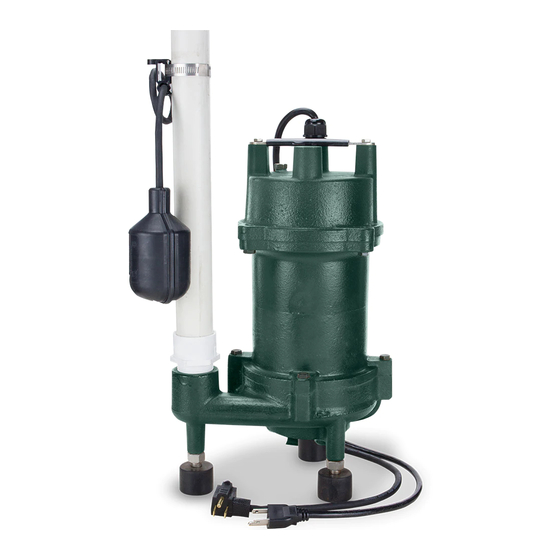
GRINDER PUMP
1
MODEL #2701
Español p. 13
SW1220 C
Advertisement
Table of Contents

Subscribe to Our Youtube Channel
Related Manuals for Zoeller 2701


Summary of Contents for Zoeller 2701
- Page 1 GRINDER PUMP ZoellerAtHome.com MODEL #2701 Zoeller is a registered trademark ® of Zoeller Co. All Rights Reserved. Español p. 13 ATTACH YOUR RECEIPT HERE Purchase Date Serial Number Questions, problems, missing parts? Before returning to your retailer, call our customer service department at 1-800-584-8089, 7:30 a.m.
-
Page 2: Safety Information
SAFETY INFORMATION Please read and understand this entire manual before attempting to assemble, operate, or install the product. • NOTE: Pumps with the “UL” mark and pumps with the “US” mark are tested to UL Standard UL778. CSA certified pumps are certified to CSA Standard C22.2 No. 108. (CUS.) DANGER •... -
Page 3: Package Contents
Ft. of Head Flow (GPM) Head (Ft.) Size Number 2701 1-1/4 in. PREPARATION Before beginning installation of product, make sure all parts are present. Compare parts with package contents list. If any part is missing or damaged, do not attempt to assemble the product. -
Page 4: General Pump Information
GENERAL PUMP INFORMATION 1. The most common application is for draining bathroom waste water. This pump is designed to shred flushable solids such as toilet paper, paper towels, feminine hygiene products and baby wipes. It can replace traditional sewage pumps when pumping to a pressurized sewer main. -
Page 5: Installation Instructions
INSTALLATION INSTRUCTIONS 1. Use a basin (not included) that is at least 18 in. wide by 30 in. deep. 30 in. 18 in. 2. Clean the basin of all debris. 3. Set the pump on a solid, level surface. A brick or block (not included) may be installed under the pump to provide a solid base. - Page 6 INSTALLATION INSTRUCTIONS 4. Install rigid 1-1/4 in. discharge pipe (not included) according to local, regional, and state codes. Discharge Pipe 5. Use a 2-step PVC glue system (not included) to join pipe and any fittings needed. 6. Attach the switch securely to the discharge pipe so that incoming water does not interfere with switch movement.
- Page 7 7. Be sure the float switch is at least 1 in. away from the side walls of the basin, and free of any obstructions through the full range of switch motion. Discharge Pipe 1 in. Minimum Switch 8. Drill a 3/16 in. hole in the discharge pipe above the Discharge pump discharge to prevent air lock.
- Page 8 10. Install a 1-1/4 in. check valve (not included) above the Check union to prevent back-flow. Valve 11. Install a 1-1/4 in. gate valve or ball valve (not included) Gate above the check valve as required by local, regional, or Valve state codes.
- Page 9 13. Attach power supply cord and switch cord to discharge pipe using cable or zip ties (not included) to allow the float switch to move freely. Cable or zip tie 14. Plug power supply cord into piggyback switch cord. Connect piggyback switch cord to a receptacle GFCI protected protected by a ground fault circuit interruptor (GFCI).
-
Page 10: Troubleshooting
INSTALLATION INSTRUCTIONS 16. Install a basin cover and gasket (not included) on the top of the basin. This will contain gases and odors, prevent debris from falling into the basin, and prevent personal injury. Basin cover gasket 17. Install a vent pipe (not included) according to local, regional, or state codes to remove gases and odors. - Page 11 Problem Possible Cause Corrective Action Pump starts and 1. Water is back-flowing into basin from 1. Install check valve. stops too often. discharge pipe. 2. Switch is defective. 2. Replace switch. 3. Check valve not functioning properly 3. Be sure check valve is installed and or leaking.
-
Page 12: Care And Maintenance
CARE AND MAINTENANCE WARNING: Always disconnect pump from power supply before handling. Inspect and test system for proper operation at least every three months. 1. Remove any build-up of debris from the switch or float, and check to be sure it moves freely. 2.
Need help?
Do you have a question about the 2701 and is the answer not in the manual?
Questions and answers