Table of Contents
Advertisement
Quick Links
Advertisement
Table of Contents

Related Manuals for Lab 12 integre4


Summary of Contents for Lab 12 integre4
- Page 1 Owner’s Manual integre4 Audiophile integrated amplifier www.lab12.gr v1.6...
- Page 2 K. Varnali 57A, Metamorfosi, 14452, Athens, Greece Tel: +30 210 2845173 Email: contact@lab12.gr Web: www.lab12.gr...
-
Page 3: Table Of Contents
Table of Contents It is yours………………………………………………………………………… Unpacking and Warnings………………………………………………… 4, 5 Features………………………………………………………..…………………. Installation & Placement………………………………..………………. Front Panel………………………………………………………..…………….. Rear Panel Connections……………………………………..…………… Remote Control…………………………………………………..…………… Interface menu structure…………………………………..…………… Connections………………………………………………………..…………… For the safety of your equipment………………………..…………. Tubes compatibility / Bias values………………………..…………. Specifications……………………………………………………..……………... -
Page 4: It Is Yours
Unpacking Lab12 integre4 should be removed from its box with care. Remove all the foam of the box before you unpack integre4. Safely store the tubes boxes until you secure integre4 at its final place. Unpack integre4 with your hands on two sides of amplifier. -
Page 5: Features
LAB12 integre4 - Audiophile integrated amplifier Warnings No user serviceable parts are included inside. Do not unscrew the cover; high voltages remain after disconnecting from mains. In case your device requires any kind of service or upgrade, please ship or take your equipment directly to Lab12 or to one of our authorized dealers or other qualified personnel. -
Page 6: Installation & Placement
LAB12 integre4 - Audiophile integrated amplifier Installation & Placement Lab12 integre4 should be placed on a solid flat surface. You should avoid placing it near a heat source as this could compromise the amplifier’s performance and reliability. You should never place another component directly on top of this amplifier. -
Page 7: Front Panel
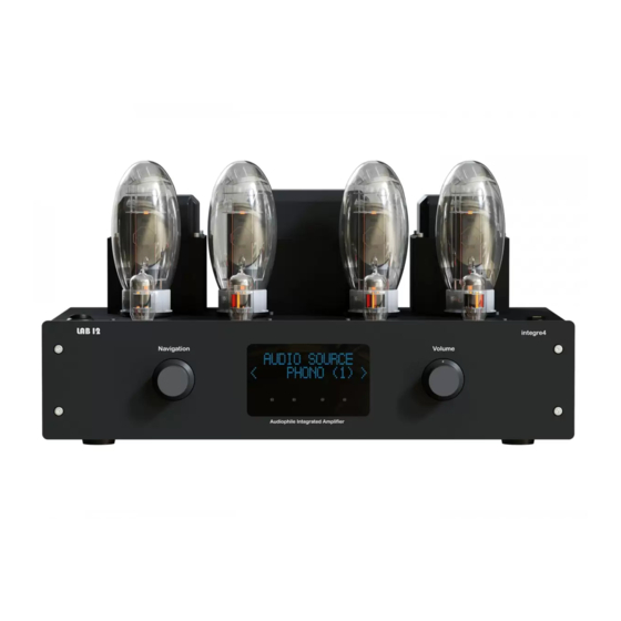
LAB12 integre4 - Audiophile integrated amplifier Front Panel Integre4 Front panel In the front panel you will see an OLED display with bias setting trimmers, the navigation rotary knob and the volume control. With the left rotary/push knob (A) you can navigate into menu structure. -
Page 8: Rear Panel Connections
LAB12 integre4 - Audiophile integrated amplifier Rear Panel Connections Integre4 Rear panel In the rear panel you will find the input and output connections. On the left side of the rear panel, you will find five pairs of single-ended RCA analog audio input connectors (A). -
Page 9: Remote Control
LAB12 integre4 - Audiophile integrated amplifier Remote Control Integre4 Remote Control You can fully control your amplifier from IR remote control RC1. At the top section of the remote control the two buttons for output volume adjustment (A) are located. -
Page 10: Interface Menu Structure
LAB12 integre4 - Audiophile integrated amplifier Interface menu structure Integre4 is a new era tube integrated amplifier; a powerful processor is responsible for the full and safe control of the device. All details can be monitored through the OLED display. -
Page 11: Connections
Connect your Speakers Connect your speakers to the additional output of integre4. Make sure about the phase and polarity of speakers, always connect ’plus’ (red) bind of integre4 to ’plus’ (red) bind of speaker and respectively the black one. You can connect any speakers with impedance from 4 to 16 ohm. -
Page 12: Tubes Compatibility / Bias Values
LAB12 integre4 - Audiophile integrated amplifier Tubes compatibility / Bias values Bellow you will find a bias chart for the most common compatible tubes for integre4. After changing tubes always turn all the bias trimmers’ counterclockwise (cold bias) with bias screwdriver, before turning on the amplifier. -
Page 13: Specifications
LAB12 integre4 - Audiophile integrated amplifier Specifications • Power: 230VAC 50Hz (115VAC 60Hz) • Power consumption: 350 VA max • Output power: 65 Watt per channel (KT150) • Frequency response: 15 Hz - 60 KHz (-1dB) • Input impedance: 50K ohm •... - Page 15 Notes: ………………………………………………………………………………………………………………………… ………………………………………………………………………………………………………………………… ………………………………………………………………………………………………………………………… ………………………………………………………………………………………………………………………… ………………………………………………………………………………………………………………………… ………………………………………………………………………………………………………………………… ………………………………………………………………………………………………………………………… ………………………………………………………………………………………………………………………… ………………………………………………………………………………………………………………………… ………………………………………………………………………………………………………………………… ………………………………………………………………………………………………………………………… ………………………………………………………………………………………………………………………… ………………………………………………………………………………………………………………………… ………………………………………………………………………………………………………………………… ………………………………………………………………………………………………………………………… ………………………………………………………………………………………………………………………… ………………………………………………………………………………………………………………………… …………………………………………………………………………………………………………………………...
- Page 16 K. Varnali 57A, Metamorfosi, 14452, Athens, Greece Tel: +30 210 2845173 Email: contact@lab12.gr Web: www.lab12.gr...
Need help?
Do you have a question about the integre4 and is the answer not in the manual?
Questions and answers