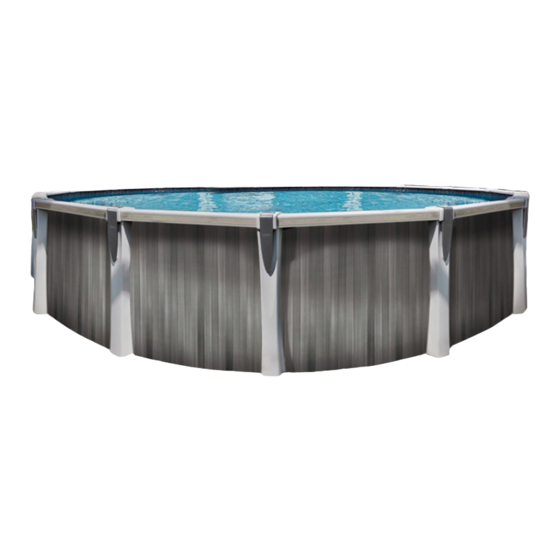
Trevi 228 Assembly Instructions Manual
Round pool
Hide thumbs
Also See for 228:
- Assembly instructions (5 pages) ,
- Assembly instructions manual (30 pages) ,
- Assembly instructions manual (15 pages)
Table of Contents
Advertisement
Available languages
Available languages
Quick Links
Dear Customer
Congratulations! You have purchased a pool of superior quality and durability. To achieve the best possible results,
follow the instructions carefully. Failure to follow the installation procedures may result in damage to your pool or
property and void your warranty. We recommend that you make a preliminary study of the instruction booklet to
familiarize yourself with the different parts of your pool. Make sure that you understand each step thoroughly before
you begin assembling.
WARNING: Be sure you have read and understand the "Safety Information" sheets
before you begin your pool installation.
WARNING: For your safety, your pool is not designed for diving and/or jumping head first.
1
When selecting a site for your pool, take into account city by-
laws regarding fences and utilities laws pertaining to electrical
cables, as well as the landscaping which you are planning once
the pool is installed.
TURF
REMOVAL DIAMETER
Please do not dive. Diving may result in permanent injury or death.
SITE PREPARATION
WALL
DIAMETER
ASSEMBLY INSTRUCTIONS
We wish you a most pleasant and refreshing summer.
Drive a stake into the ground at the center of the site. Using a meas-
uring tape, draw a circle 15 cm to 20 cm (6" to 8") longer in radius
than the pool, depending on the width of the uprights (See Illustra-
tion 1.1).
Remove all grass from the area which you have just outlined.
Make sure to order the required quantity of sand and stone dust
(See Chart).
Illustration 1.1
40302_V2_2021-01-23
ROUND POOL
MODEL 228-230-248
Advertisement
Table of Contents

Related Manuals for Trevi 228


Summary of Contents for Trevi 228
- Page 1 40302_V2_2021-01-23 ASSEMBLY INSTRUCTIONS ROUND POOL MODEL 228-230-248 Dear Customer Congratulations! You have purchased a pool of superior quality and durability. To achieve the best possible results, follow the instructions carefully. Failure to follow the installation procedures may result in damage to your pool or property and void your warranty.
- Page 2 SITE PREPARATION (continued) Chart 3,05 m (10’) 1,72 m (5’8”) 3,05 m (11’6”) 9,14 m (30’) 4.57 m (15’ 8") 9.14 m (31’ 4") 2 1/2 Tons 2 Tons * If you use only sand, add stone dust tonnage to sand. SITE LEVELLING Level the edge of the circle, from the turf removal line up to 30 cm Optional...
- Page 3 BOTTOM DRAIN ASSEMBLY (if applicable) Dig a hole 30 cm (12") wide by approximately 25 cm (10") deep in the center of the circumference. From the center hole to the projected location of the pool motor, dig a 15 cm (6") wide trench. Place the removed soil aside to be used later to cover the hose.
-
Page 4: Wall Installation
WALL INSTALLATION Add sand. Begin inserting the wall into the bottom wall tracks in the middle of Before uncoiling the wall, make sure the pre-punched holes for the a joiner plate. At first, the wall is kept in place with one or two stakes skimmer and pump return are at the top and facing the planned lo- and strings (or extra persons). - Page 5 WALL INSTALLATION (continued) Chart 3,05 m (10’) 9,60 m (31’ 6") 9,14 m (30’) 28,72 m (94’ 3") SAND BASE FINISHING You can now spread approximately 10 cm (4") of compacting sand all around the inside base of the wall in order to protect the liner WALL from the cutting edges of the bottom wall tracks and the stone dust 30 cm (12")
- Page 6 VINYL LINER INSTALLATION (continued) RESIN TOP STEEL TRACK TOP TRACK U-BEAD LINER WALL Start the vacuum cleaner to allow the liner to adhere to the wall and Lift up a section of the liner over the top of the wall leaving a 10 cm check for excess tension at the bottom or for wrinkles.
- Page 7 UPRIGHT POST INSTALLATION Attach the uprights to the bottom plate with two (2) screws “Z”, which you will find in the hardware bag. Uprights must be installed outside the flanged part of the bottom plate and into the two notchs of the bottom track. ‘’Z’’...
- Page 8 SEAT CAP INSTALLATION Put the seat cap on the inside section of the seat and interlock with the upright. Secure the seat cap with one (1) screw “Z”. Snap the cap logo on top of the upright and secure the bottom with one (1) screw ‘’Z’’.
-
Page 9: Parts List
FILTRATION SYSTEM ASSEMBLY Assemble skimmer, inlet, drain, filter, pumps, hoses according to separate manufacturer’s instructions. Note: See 'Safety Information" Manual. PARTS LIST TOP SEAT UPRIGHT 52’’ TOP PLATE SEAT CAP BOTTOM PLATE BOTTOM TRACK PLASTIC COUPLER TOP TRACK POOL WALL (Finish lenght, inch) BOLT &NUT FOR 52’’... -
Page 10: Safety Information
SAFETY AND FUN GO TOGETHER! SAFETY INFORMATION Read this before installing your above-ground pool. 12 775, Brault Street, Mirabel, Quebec, Canada J7J 0C4 Phone: 1 800 44-TREVI (1 800 448-7384) Fax: 1 866 777-0167... -
Page 11: General Information
If you need more stickers or if some are missing, you can ABILITY SHOULD THIS STEP BE OMITTED. order these at info@trevi.ca or by calling 1 800 44TREVI Before installing your pool, you should check local regulations such... - Page 12 USAGE SAFETY INFORMATION...
-
Page 13: Instructions D'assemblage
40302_V2_2021-01-23 INSTRUCTIONS D’ASSEMBLAGE PISCINES RONDES MODÈLE 228-230-248 PRÉPARATION DE L’EMPLACEMENT Choisissez l'emplacement idéal pour votre piscine en tenant Plantez un pieu au centre de l'emplacement et, à l'aide d'un ruban à compte des lois municipales sur la distance des clôtures, celles mesurer, tracez un cercle dont le rayon sera de 15 cm à... - Page 14 PRÉPARATION DE L’EMPLACEMENT (suite) Tableau * Si vous n’utilisez que du sable, additionnez le tonnage de la poussière de roche à celui du sable. NIVELLEMENT DU TERRAIN Vous devez ensuite niveler le pourtour du cercle à partir de la limite Facultatif de déterrement jusqu'à...
- Page 15 INSTALLATION DU DRAIN DE FOND (optionnel) Creusez un trou de 30 cm (12") de largeur par environ 25 cm (10") de profondeur en plein centre de la circonférence. Creusez une tranchée d'environ 15 cm (6") de largeur à partir du trou central jusqu'à...
- Page 16 INSTALLATION DU MUR D’ACIER Déversez le sable. En commencant au centre d'une plaque, insérez le mur d’acier dans Avant de dérouler le mur d’acier, assurez-vous que les orifices la rainure inférieure. Maintenez tout d'abord le mur en place à l'aide prévus pour l'écumoire et le retour d'eau se trouvent bien au haut d'une ou deux barres de soutien ou avec l'aide d'autres personnes.
- Page 17 INSTALLATION DU MUR D’ACIER (suite) Tableau LONGUEUR RÉELLE DU MUR D’ACIER 3,05 m (10’) 9,60 m (31’ 6") 9,14 m (30’) 28,72 m (94’ 3") FINITION DU FOND Étendez maintenant environ 10 cm (4") de sable à compactage au bas du mur intérieur de façon à former un remblai destiné à protéger MUR D'ACIER la toile des extrémités coupantes des rainures inférieures et de la 30 cm (12")
- Page 18 INSTALLATION DE LA TOILE DE VINYLE (SUITE) haut par dessus la toile. L'aspirateur est ensuite mis en marche pour que la toile adhère à la paroi du mur. C'est à ce moment que vous verrez si elle est trop RAINURE DU RAINURE DU HAUT HAUT EN EN RÉSINE...
- Page 19 NSTALLATION DES POTEAUX Fixez les poteaux aux plaques du bas à l’aide de deux (2) vis “Z” que vous trouverez dans le sac de quincaillerie. Le poteau rentre dans les deux encoches de la rainure du bas. Il est à noter que les poteaux s’installent à l’extérieur de la partie retroussée de la plaque du bas.
- Page 20 INSTALLATION DU COUVRE-JOINT Accrochez le couvre-joint sur le rebord intérieur des sièges et l’en- clencher sur le poteau. Fixez-le à l’aide d’une vis “Z” sur le dessus. Accrochez le cap logo dans la partie superieur du poteau et fixez- le à l’aide d’une (1) vis ‘’Z’’ à la base.
-
Page 21: Liste Des Pièces
MONTAGE DU SYSTÈME DE FILTRATION Assembler l’écumoire, le drain de fond, le retour d’eau et le système de filtration selon les instructions d’assemblage des manufacturiers. Note : Voir les “Informations de sécurité”. LISTE DES PIÈCES SIÈGE POTEAU 52’’ PLAQUE DU HAUT COUVRE-JOINT DE SIÈGE PLAQUE DU BAS RAINURE DU BAS... -
Page 22: Consignes De Sécurité
ET AVANT TOUT PAR LA SÉCURITÉ CONSIGNES DE SÉCURITÉ Veuillez lire ceci avant de procéder à l’installation de votre piscine hors terre. 12 775, rue Brault, Mirabel, Québec, Canada J7J 0C4 Téléphone : 1 800 44-TREVI (1 800 448-7384) Télécopieur : 1 866 777-0167... -
Page 23: Renseignements Généraux
Si vous désirez obtenir des autocollants addition- triques sont nécessaires. Il se peut que les règlements de votre lo- nels, vous pouvez en commander à l’adresse INFO@TREVI.CA ou calité exigent que votre piscine soit installée selon certaines marges au 1 800 44TREVI. - Page 24 CONSIGNES DE SÉCURITÉ LORS DE L’UTILISATION DE LA PISCINE...
Need help?
Do you have a question about the 228 and is the answer not in the manual?
Questions and answers