Table of Contents
Advertisement
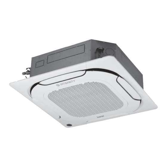
FOUR WAY CASSETTE
DIVERSE
MDV-D09Q4/VN1-E(At), MDV-D12Q4/VN1-E(At), MDV-D15Q4/VN1-E(At), MDV-D18Q4/VN1-E(At),
MDV-D24Q4/VN1-E(At), MDV-D28Q4/VN1-E(At), MDV-D32Q4/VN1-E(At), MDV-D36Q4/VN1-E(At),
MDV-D40Q4/VN1-E(At), MDV-D48Q4/VN1-E(At).
INSTALLATION AND
OPERATION MANUAL
Thank you very much for purchasing our air conditioner.
Before using your air conditioner, please read this manual carefully and keep it for future reference.
MAN-IO-IC4DI-1120
intensity.mx
Advertisement
Table of Contents

Related Manuals for intensity Black Series


Summary of Contents for intensity Black Series
- Page 1 MDV-D09Q4/VN1-E(At), MDV-D12Q4/VN1-E(At), MDV-D15Q4/VN1-E(At), MDV-D18Q4/VN1-E(At), MDV-D24Q4/VN1-E(At), MDV-D28Q4/VN1-E(At), MDV-D32Q4/VN1-E(At), MDV-D36Q4/VN1-E(At), MDV-D40Q4/VN1-E(At), MDV-D48Q4/VN1-E(At). INSTALLATION AND OPERATION MANUAL Thank you very much for purchasing our air conditioner. Before using your air conditioner, please read this manual carefully and keep it for future reference. MAN-IO-IC4DI-1120 intensity.mx...
-
Page 3: Table Of Contents
Contents • Use only electrical cables that fulfil the specifications. All wiring on Installation Manual................1 site must be carried out in accordance with the connection diagram Accessories..................3 attached to the product. Make sure that there are no external forces 1. Before Installation ................4 acting on the terminals and wires. - Page 4 Caution • Install the water discharge piping according to the steps described in this manual, and make sure that the water discharge is smooth, and the piping is properly insulated to prevent condensation. Improper installation of the water discharge piping may lead to water leakage, and damage the indoor furniture.
-
Page 5: Accessories
Accessories Verify that the air conditioner includes the following accessories. Code Installation Manual Washer Installation board M6 screw Insulation casing for copper pipe Foam (250x250x8) Foam (60x100x5) Insulation casing for water discharge piping Ring clamp for water discharge pipe Tightening band Soft flexible hose for water discharge Brass nut Accessories to purchase locally... -
Page 6: Before Installation
1. Before Installation 1. Determine the route to move the unit to the installation site. 2. First unseal and unpack the unit. Then, hold the seats of the hanger (4 pcs) to move the unit. Refrain from exerting force on other parts of the unit, especially the refrigerant piping, water discharge piping, and the plastic parts. - Page 7 1. Drill 910x910mm square holes into the ceiling based on the layout of the Original concrete slab structure installation board (accessory 4). See Figure 3.5. The centre of the ceiling opening should match the centre of the body of the ...
- Page 8 Refrigerant piping vent (gas side D) Air conditioner body Refrigerant piping vent (liquid side C) ϕ32 (outer diameter of water discharge pipe) Screw M6x12 (accessory) Installation board Figure 3.8 Caution • Before you install the indoor unit, make sure that you remove the buffers used for transportation between the fan and the Top view pipe socket (see Figure 3.9).
- Page 9 Drain pan hook Panel hook Piping side 45° Drain side Figure 3.13 Swing motor Hook Caution screw Phillips • Do not place the panel such that it faces downwards or leans screwdriver against the wall. Do not place it on a protruding object either. •...
- Page 10 Distribution duct No gap allowed Distribution duct Distribution duct Figure 3.18 Φ75 The side with EXV cannot be connected with distribution duct. 1. First loosen the nut Distribution duct Fresh air Figure 3.22 2. Adjust the nut Size (mm) 09~28 models 32~48 models Figure 3.19 3.3.4 First hang the air inlet grille on the panel, and then connect...
-
Page 11: Refrigerant Piping Installation
4. Refrigerant Piping Installation Before the socket cap is installed on the pipe socket, apply some refrigerant oil on the socket (both inside and outside), and then rotate it three or four 4.1 Length and Drop Height Requirements for the Piping times before you tighten the cap. -
Page 12: Water Discharge Piping Installation
5. Water Discharge Piping Installation 5.2 Water Discharge Test 5.1. Water Discharge Piping Installation for Indoor Unit Before the test, make sure that the water discharge pipeline is smooth, and check that each connection is sealed properly. 1. Use PVC pipes for the water discharge pipes (outer diameter: 37~39 mm, Conduct the water discharge test in the new room before the ceiling is paved. - Page 13 Refer to Tables 6.1 and 6.2 for the specifications of the power cord 6.1 Power Cord Connection and communication wire. A wiring capacity that is too small will Use a dedicated power supply for the indoor unit that is different cause the electrical wiring to become too hot, and lead to accidents ...
- Page 14 6.3.2 Communication wiring between the indoor unit and wired Table 6.3 (optional) controller Nominal cross-sectional area (mm Rated current The wired controller and the indoor unit can be connected in different of appliance(A) Flexible cords Cable for fixed wiring manners, depending on the forms of communication. ≤3 0.75 1) For a bidirectional communication mode:...
-
Page 15: On-Site Configuration
The network address and the indoor unit address are the same, 6.4 Handling the Electrical Wiring Connection Points and does not have to be configured separately. Once the wiring and connections are done, use tie straps to Once the address settings are completed, mark the address of ... -
Page 16: Test Run
Once the installation is completed, please keep the manual properly for future reference. When this air conditioner is handed over to other users, make sure that the manual is included with the handover. Auto restart function enabled Warning Auto restart function disabled •... -
Page 17: Part Names
Do not dispose of this product as unsorted • Do not use the unit until the qualified technician instructs you that it is safe • waste. It must be separately collected to do so. and processed. Ensure that all • Do not place appliances that produce naked flames in the path of the airflow applicable legislation regarding the from the unit. -
Page 18: Air Conditioner Operations And Performance
Infrared signal receiving window Digital display ALARM Timer Anti-cold air / indicator defrosting indicator Operation indicator Figure 10.2 Table: Display panel output under normal operating conditions. Display output Digital display panels Unit state Unit state Digital display Operation indicator Standby flashes slowly Shutting-down All indicators off... -
Page 19: Adjusting Air Flow Direction
Method for cleaning the air filter a. The air filter can prevent the dust or other particles from entering the unit. If the filter is blocked, the unit will not work well. Clean the filter every two weeks when you use it regularly. b. -
Page 20: Symptoms That Are Not Faults
14. Symptoms That Are Not Faults The following symptoms may be experienced during the normal operation of the unit and are not considered faults. Note: If you are not sure whether a fault has occurred, contact your supplier or service engineer immediately. - Page 21 15.2 Unit troubleshooting A power cut has occurred (the power to the Wait for the power to come back on. premises has been cut-off). Power on the unit. This indoor unit forms part of an air conditioning system that has multiple indoor units that are all connected.
- Page 22 15.3 Remote controller troubleshooting Warning: Certain troubleshooting steps that a professional technician may perform when investigating an error are described in this owner's manual for reference only. Do not attempt to undertake these steps yourself – arrange for a professional technician to investigate the problem. If any of the following errors occur, power the unit off and contact a professional technician immediately.
- Page 23 15.4 Error codes With the exception of a mode conflict error, contact your supplier or service engineer if any of the error codes listed in Table 7-3 are displayed on the unit's display panel. If the mode conflict error is displayed and persists, contact your supplier or service engineer. These errors should only be investigated by a professional technician.
Need help?
Do you have a question about the Black Series and is the answer not in the manual?
Questions and answers