Table of Contents
Advertisement
Quick Links
Advertisement
Table of Contents

Related Manuals for Nakanishi Sonic Cutter ZERO

Summary of Contents for Nakanishi Sonic Cutter ZERO
-
Page 2: Table Of Contents
Thank you for your purchase of Sonic Cutter ZERO Ultrasonic Cutter. This product is a device that can be used for cutting and deburring of plastic materials, rubber, urethane, etc. as well as for cutting sheets, cloths, etc. Please read this manual carefully before use. We hope you will enjoy using this product for many years to come. -
Page 3: Safety Precautions
Safety Precautions Please read the operation manual thoroughly, make sure you understand all warnings and cautions prior to operating the system and only use the system in the manner intended. These warnings and cautions are intended to avoid potential hazards that could result in personal injury or damage to the device. - Page 4 Safety Precautions Volts Total length of cord Ampere Rating 120V 7.5m (25ft.) 15m (50ft.) 30m (100ft.) 45m (150ft.) 240V 15m (50ft.) 30m (100ft.) 60m (200ft.) 90m (300ft.) Not More More Than Than Not Recommended Use the table above for your correct voltage. WARNING For safety reasons, always wear protective gloves and goggles when using this product.
- Page 5 Safety Precautions CAUTION The operating environment for this product is 10 - 40°C (75 - 104ºF),, humidity is 30 - 75% RH,, and air pressure is 700 - 1,060 hPa. Also, use the controller in a non-condensing environment. If used beyond this range, it may cause malfunctions or damage.
-
Page 6: Product Information
Product Information 2 – 1 Bundled items After opening the package, please check that the contents of "Table - 1 List of Contents " are inorder. In the unlikely event that any of the contents of the package are inadequate, please contact " 8 – 2 Contact for inquiries "... -
Page 7: Names Of Parts
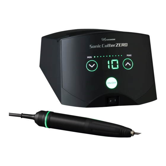
Product Information 2 – 2 Names of parts Overall Structure Handpiece Control panel Controller Main power switch Handpiece socket Pedal Inlet with power Foot switch socket supply fuse Back of controller Foot switch (Optional) - Page 8 Product Information Control panel indication name function Displays the power level. About the display. Power level indicator [MAX] (lit ).Indicates the increase or decrease of the output level by repeatedly lighting and blinking in 21 step variable . Displays the watt, amplitude, and ERROR values.
- Page 9 Product Information Handpiece name Note This cap to protect the blade from direct contact with the hand. If Blade Protector Cap the inner O-ring is damaged or lost, please use the spare O-ring included in the package. Please purchase replacement blades at a tool store or stationery Blade store.
-
Page 10: Preparation Before Use
Preparation before use 3 – 1 Connecting the main power cord Make sure the main power switch is in the OFF Insert the main power cord into the Inlet with power position. supply fuse. Then plug it into a commercial power outlet. -
Page 11: Replacing The Blade
Preparation before use 3 – 4 Replacing the blade The blade is attached to the handpiece. Make sure the blade is securely attached before use. Remove the cap by pulling it straight off. Tighten the set screws with a hexagon wrench. When installing a new blade, tighten it in the center so that both ends of the blade do not touch the horn. -
Page 12: How To Use
How to use Basic Operation Power ON The LED on the control panel lights up. Power level adjustment Press and hold down the key to activate the key repeat function. UP key DOWN key 1, 4 Startup / Stop You can start and stop the program in one of the following two ways (1) Manual ON / OFF (2) When using the foot switch(Optional) Activated the handpiece by... -
Page 13: Maintenance
Maintenance 5 – 1 Fuse replacement The fuse box is set in a Inlet with power supply fuse. Push the claws of the cap firmly into the inlet box. Push the claws on both sides of the cap inward and pull it out. -
Page 14: Setup
Setup Various settings can be made for your use from below. 6 – 1 User setting operations Set the Main power switch to OFF. Press the UP key to select the item you want to set. The display unit will display the following order*2: " "... -
Page 15: Setting The Forced Stop Time When Not In Use
Setup 6 – 2 Setting the forced stop time when not in use This function forces the handpiece to stop if the handpiece has been left unused with the ON / OFF key turned on. Press the DOWN key to change the setting value. The Indicator shows the following order "... -
Page 16: Setting The Foot Switch
Setup 6 – 5 Setting the foot switch The setting can be changed from pressing the foot switch to start (ON) or release to stop (OFF), to pressing the foot switch to start (ON) or pressing it again to stop (OFF). Press the DOWN key to change the setting value. -
Page 17: Troubleshooting
Trouble-shooting 7 – 1 Error code If a problem occurs with the product, an error code will be displayed on the display unit on the operation panel. Stop the operation at once. Press the ON / OFF key, or step on the footswitch again or turn it back on and see if the error is resolved. -
Page 18: Failure Causes And Countermeasures
Trouble-shooting 7 – 2 Failure causes and countermeasures A malfunction? If you think that this is the case, please check the following again before you call for repairs. Symptoms Visual Checklist Cause Countermeasure Main power cord is not Plug the main power cord into plugged in. - Page 19 Trouble-shooting Symptoms Visual Checklist Cause Countermeasure Replace it with a standard No standard blade are used. blade. Loose blade. Retighten the blade. The LED on the The vibration is ON / OFF key is Adjust the UP and DOWN weak. The Power level indicator is keys to the output appropriate in the minimum position.
-
Page 20: After Sales Service
(closed Saturday, Sunday and Public Holidays) Telephone No. : +81 289 64 3520 e-mail : webmaster-ie@nsk-nakanishi.co.jp 8 – 3 Product disposal When disposal of products is necessary, follow the instructions from your local government agency for proper disposal of industrial components. -
Page 21: Specifications
Specifications 9 – 1 Specifications Controller Model Sonic Cutter ZERO Controller (NE337) Oscillation frequency 38kHz - 40kHz frequency control Auto-tracking system Outputs 30W (maximum) Output adjustment 21 steps variable Rated input 100V AC - 240V, 50/60 Hz,24 W Applicable Fuses T1.6AH 250V... -
Page 22: Protection Sircuitry
Specifications 9 – 3 Protection Circuitry Protection Features 30W or more in detected, the unit will stop operating for safety. (see "7 – 1 Error code"03") If the handpiece is pulled out of the connector during operation, it will stop. To prevent the handpiece from forgetting to turn it off, the handpiece will stop automatically if it is still unused when it is on.
Need help?
Do you have a question about the Sonic Cutter ZERO and is the answer not in the manual?
Questions and answers